1054
A 16 channel head-only pTX array using high efficiency in-bore RFPAs at 3T1Dept of Radiology, Case Western Reserve University, Cleveland, OH, United States, 2Siemens Healthcare GmbH, Erlangen, Germany
Synopsis
Parallel transmit (pTX) has been proposed as a solution to flip angle inhomogeneity and SAR at ultrahigh fields, as well as safety hazards with implantable devices. However, pTX systems come at high cost, partially due to the use of remotely located linear RF power amplifiers (RFPAs), which have poor power efficiency and rely on costly RF power cables to couple power to the subject. Here we demonstrate a 16 channel transmit array utilizing high efficiency RFPA modules inside the scanner bore. They RFPAs can deliver a total of over 1kW to the array while only cooled by natural convection.
Purpose
Parallel transmit (pTX) has been proposed as a solution to B1+ transmission challenges at ultrahigh fields and with implantable devices1,2. However the cost of pTX systems based on remotely located linear RFPAs is high due to the low efficiency of the RFPAs and the need to carry RF power into the bore via cables. Previous work has demonstrated the use of on-coil linear RFPAs3,4, but their heat dissipation inherently limits the power density of the array. Previous work has demonstrated RFPA modules with high power efficiency and density capable of operating in or near the MRI bore5,6. Here we demonstrate a 16 channel head-only transmit array utilizing these modules.Methods
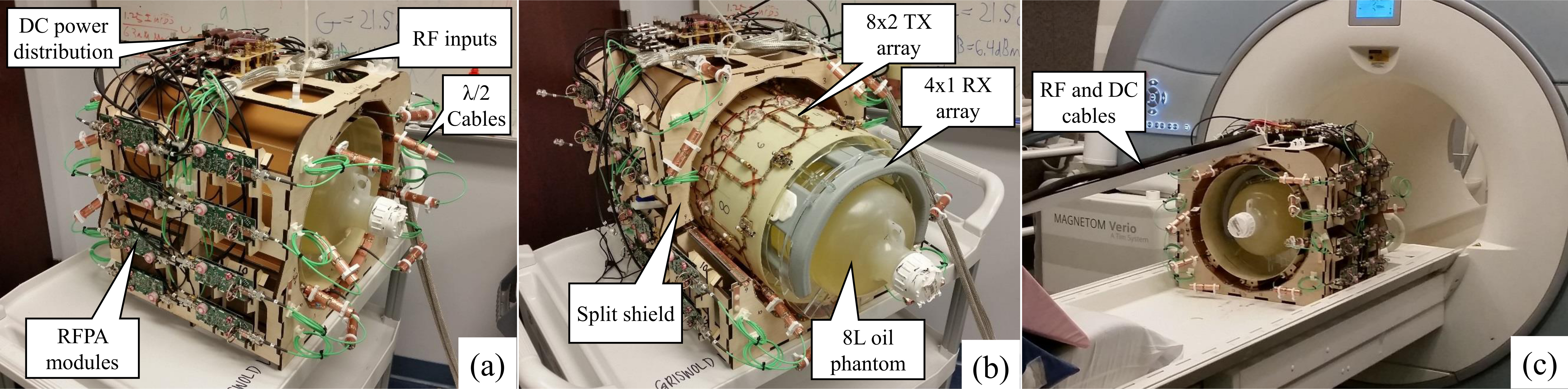
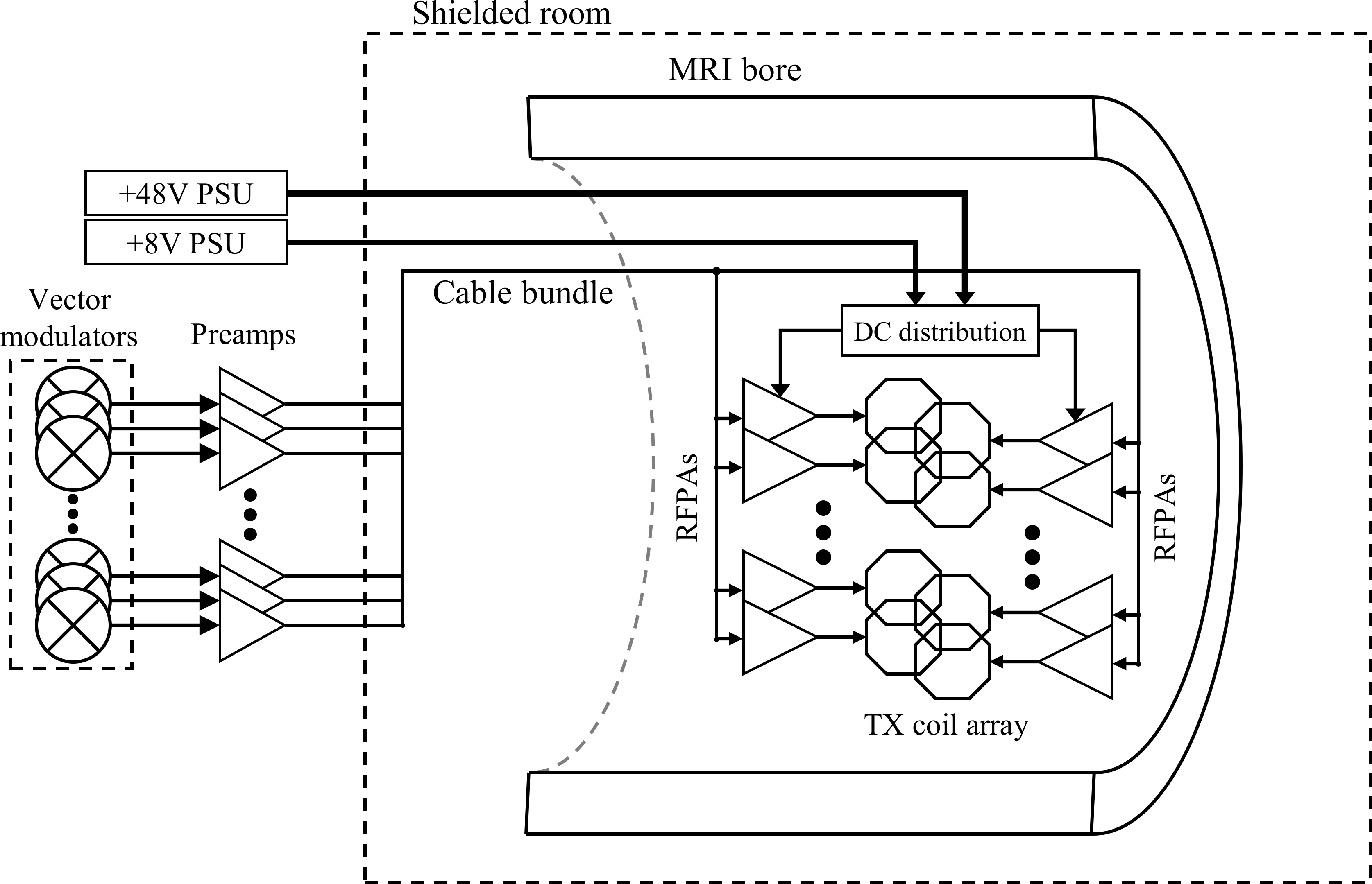
Coil array: The TX array is a 8x2 cylindrical array of loop elements. The two rows are interleaved by π/8, and each element is overlap decoupled with its four nearest neighbors. The two diagonal next-nearest neighbors are decoupled using variable transformers. The array is RF shielded in order to provide consistent behavior on the benchtop and in the scanner bore. The TX coil array diameter was 31cm, while the shield diameter was 36.5cm. Each coil is tuned and matched to 50Ω using an impedance transformer similar to that used for preamplifier decoupling7. Figure 1 shows photos of the array. Figure 2 shows a diagram of the full transmit chain.
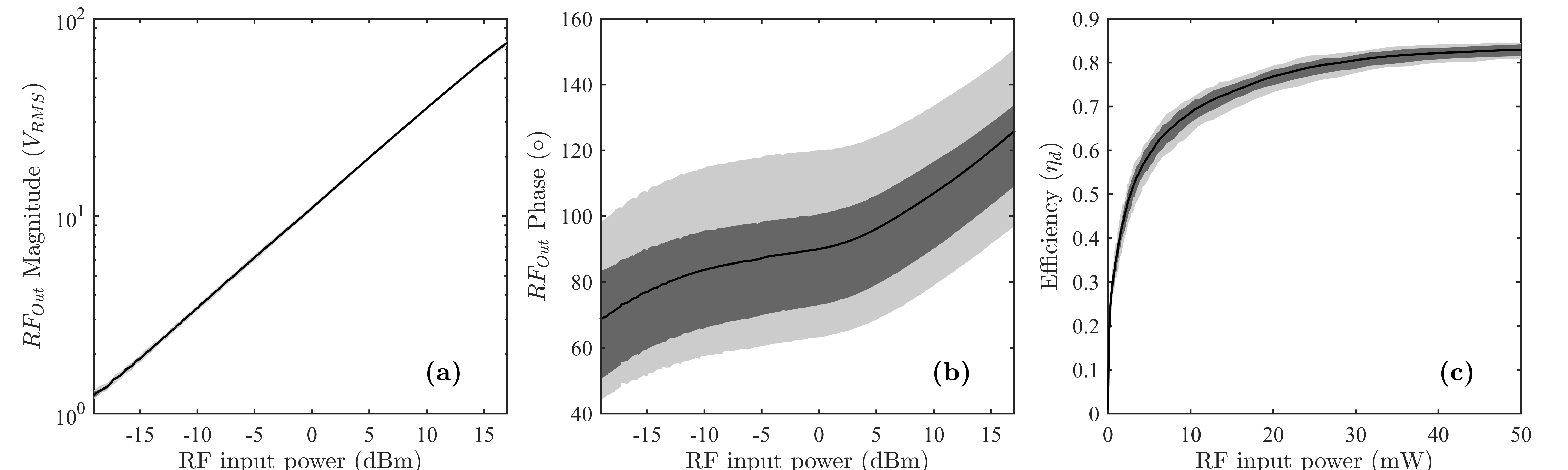
RFPA modules: High efficiency RFPA modules are used to drive each element5. Figure 3 shows plots of the output power, phase, and efficiency of the amplifiers as a function of input power. The RFPAs were mounted on the sides of the shield, and connected to the coil ports with λ/2 lengths of coax cable. Each RFPA is controlled by a low power RF input, provided via a RG316 cable. Two DC feeds (+8V for the controllers, +48V for the RFPAs), are split above the array. Independent RF control inputs are produced using a 16 channel RF splitter and vector modulator cabinet (Siemens Healthcare GmbH)
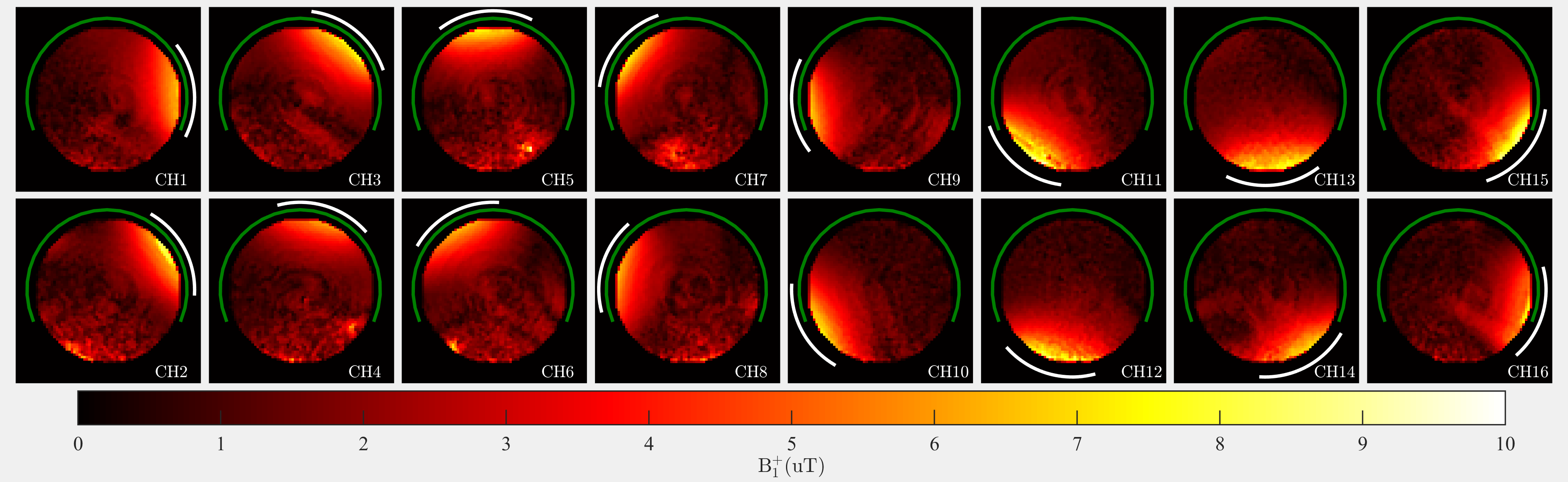
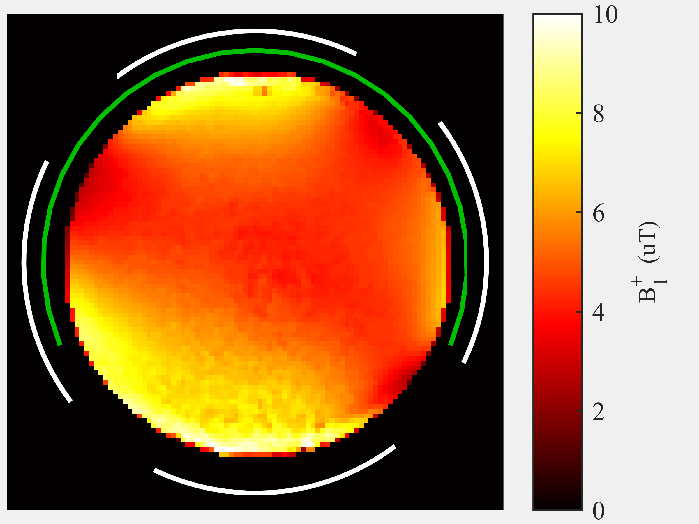
Imaging experiments: B1+ maps in an oil phantom were acquired for each element using the Bloch-Siegert method8. Predistortion was used to correct for the static nonlinearity of each RFPA. RF receive was done using a 4 channel body matrix coil wrapped around the phantom. We also measured the B1+ map from an excitation using four channels simultaneously. The current draw from the 48V DC supply was monitored during imaging sequences to measure the total power consumed by the array.
Results
Coil performance: Each coil experienced the highest coupling to its two lateral next-nearest neighbors (worst case S21=-15dB), while all others are kept below -22dB. Additional decoupling is also provided by the impedance transformers and the mismatch of the RFPAs9.
RFPA performance: The RF output and efficiency of each RFPA module was measured, and the results are plotted in Figure 2. Each amplifier was capable of providing at least PO=110W to a matched load. However, currently our preamplifiers limit the output power to just PO=90W per channel.
Imaging experiments: Figure 4 shows the B1+ map of each element at PO=90W. Each element was capable of independently generating nearly 2µT at isocenter. Dark bands and bright spots in some maps are due to coupling between some coil elements and the inputs of the RFPAs of other channels. Figure 5 shows a B1+ map using four elements simultaneously at PO=90W for each amplifier. The calculated B1+ was 4.5µT at isocenter, and the measured peak current drawn from the 48V supply rail during the pulse was 9.2A.
Discussion and Conclusion
Here we have
demonstrated the first 16 channel pTX array using in-bore RFPAs. The system is
currently not for human use. The RFPAs were capable of delivering over 1kW of
peak power to the array, despite being a fraction of the weight and size of
conventional systems. Future work will utilize the array for a variety of
applications, from B1+ shimming to multiband excitation
and Magnetic Resonance Fingerprinting10. It should be stressed that the
coil array is not designed for optimal sensitivity, but rather to provide a
suitable test bed for the RFPAs. There is substantial room for optimization in both
the transmit and receive element design. Modifying the RFPA modules to include
a T/R switch and an LNA would allow us to eliminate the receive-only array,
thus bringing the coils closer to the subject and increasing sensitivity. Revision
of the preamplifiers and cable distribution scheme will allow for operation at
full output power while reducing coupling to the RFPA inputs.Acknowledgements
This work was supported by Siemens Healthcare and NIH Grants 5R01-EB016728 and 5R01EB017219. We would also like to thank Sherry Huang and Maya Gulani for assistance in constructing the array, as well as Ke Cheng Liu and Frank Dessoffy for research assistance.References
1. Van de Moortele, P. et al. B1 destructive interferences and spatial phase patterns at 7 T with a head transceiver array coil. Magnetic Resonance in Medicine 54, 1503–1518 (2005).
2. Eryaman, Y. et al. A Simulation Based Validation of a pTx Pulse Design Strategy Using Implant-Friendly Modes for Patients with DBS Implants. 22nd annual ISMRM (2014).
3. Kurpad, K. N., Boskamp, E. B. & Wright, S. M. Implementation of coil integrated RF power MOSFET as voltage controlled current source in a transmit phased array coil. 12th annual ISMRM (2004). 4. Kurpad, K. N., Boskamp, E. B. & Wright, S. M. Eight channel transmit array volume coil using on-coil radiofrequency current sources. Quant Imaging Med Surg 4, 71–78 (2014).
5. Twieg, M. & Griswold, M. A. High efficiency radiofrequency power amplifier module for parallel transmit arrays at 3 Tesla. Magnetic Resonance in Medicine (2016). doi:10.1002/mrm.26510
6. Gudino, N., Riffe, M., Heilman, J. & Grizwold, M. 1.5T On-Coil Current-Mode Class-D (CMCD) Amplifier with Amplitude Modulation Feedback and Voltage-Mode Class-D (VMCD) Preamplifier. 18th annual ISMRM (2010).
7. Reykowski, A., Wright, S. M. & Porter, J. R. Design of matching networks for low noise preamplifiers. Magn Reson Med 33, 848–852 (1995).
8. Sacolick, L. I., Wiesinger, F., Hancu, I. & Vogel, M. W. B1 mapping by Bloch-Siegert shift. Magnetic Resonance in Medicine 63, 1315–1322 (2010).
9. Twieg, M. & Griswold, M. A. Optimizing the Current-Mode Class D (CMCD) Amplifier for Decoupling in pTX Arrays. 23rd annual ISMRM (2015).
10. Ma, D. et al. Magnetic resonance fingerprinting. Nature 495, 187–192 (2013).
Figures