1053
Size-adaptable 13-channel receive array for brain imaging in human neonates at 3 T1NeuroPoly Lab, Institute of Biomedical Engineering, Polytechnique Montreal, Montreal, QC, Canada, 2Medical Biophysics Center, University of Oriente, Santiago de Cuba, Cuba, 3Sainte-Justine Hospital University Center, Montreal, QC, Canada, 4Department of Pediatrics, Faculty of Medicine, University of Montreal, Montreal, QC, Canada, 5Montreal Heart Institute, Montreal, QC, Canada, 6Department of Radiology, Radio-oncology and Nuclear Medicine, University of Montreal, Montreal, QC, Canada, 7Institute of Biomedical Engineering, University of Montreal, Montreal, QC, Canada, 8Functional Neuroimaging Unit, CRIUGM, University of Montreal, Montreal, QC, Canada
Synopsis
A size-adaptable receive array that can accommodate a variety of heads in a pediatric population (27-week-premature to 1.5-month-old) is proposed. Thirteen spherically distributed loops can move in radial and axial directions to maximize their proximity to the subject. Decoupling between elements is ensured by strong preamplifier decoupling (-27 to -33 dB). Tests on a scanner with two phantoms (8 and 10 cm in diameter) resulted in higher SNR with the proposed coil compared to 8-Ch and 32-Ch commercial head coils. The method restricts head motion and could be of interest for other size-varying body parts, such as breast and limbs.
Purpose
Head dimensions and shape of the paediatric population, mainly during the first weeks of life, are highly variable. While higher image SNR is obtained by means of receive arrays positioned close to the subject, standard adult coils and paediatric birdcages are mostly used to scan neonates resulting in sub-optimal image quality due to their large dimensions. Optimized but not commercially available solutions were proposed, such as adjustable arrays 1,2, as well as sets of coils to cover specific age ranges, including neonates 3,4. The goal of this work was to develop a size-adaptable receive array for a variety of newborn heads to increase image SNR compared to fixed-size coils.Methods
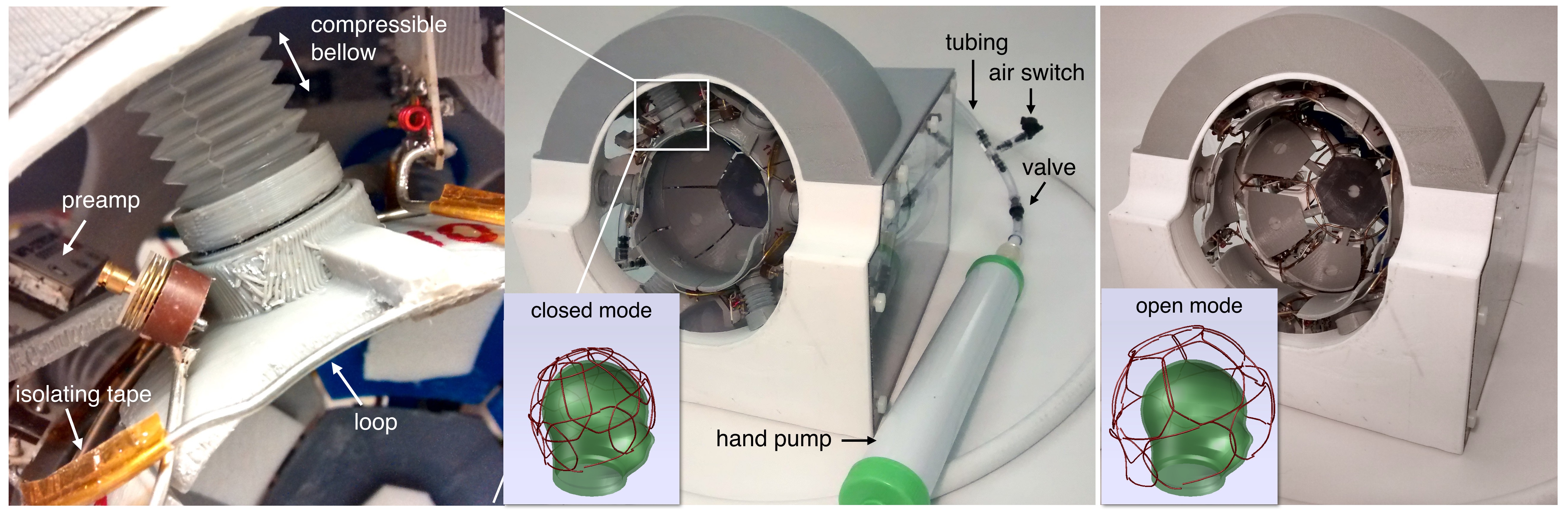
The array was designed to cover newborn head dimensions from 2-week-premature to 1.5-month-old, considering the 50th percentile head circumference. The shape of the structure can adapt to nearly spherical loads from 8 to 12.5 cm, allowing space for padding. 13 elements made of 16 AWG copper wire loops, directly connected to low input impedance preamps (MPB-127R73-90, Hi-Q.A. Inc., ON, Canada) were distributed around the brain region (Fig.1).
Element shapes were determined with the aid of an electromagnetic simulation software (FEKO, Altair, MI, US) to completely cover the region of interest along the whole size range. Impedance, preamp decoupling, isolation between channels, B1- field and SNR, were evaluated for five different load dimensions. Geometrical decoupling was established approximately in the middle of the size range while a coupling coefficient of +/- 0.16 was selected for the ends. Low stiffness plastic bellows connected to a common tubing and a hand vacuum pump form a pneumatic system used to move the elements. The coil is initially expanded to the largest dimensions by creating a negative pressure to compress the bellows. After the subject is placed, a pneumatic switch is opened to allow the air to enter in the system. The elements move towards the subject gently pushed by the bellows. Each element can move independently in radial directions and tilt around its axis to adapt its final position to a specific head section. 3D printing technology was used to build most coil parts and phantoms. Bench tests were performed with three phantoms (8, 10 and 12.5 cm in diameter) corresponding to the smallest, medium and largest coil dimensions. They were filled with a solution that simulates the head loading (Ɛr=50, σ=0.6 S/m, ρ=1310 kg/m3). All elements were tuned and matched on the bench to 127.73 MHz and 172-183 Ohms respectively with the 10cm phantom. Scanner tests were conducted in a MR750 3T scanner (GE Healthcare, Chicago, IL, US). Two phantoms (8 and 10 cm) were scanned with the proposed coil and with two available commercial adult head coils (8 and 32-channel). Axial and sagittal SPGR sequences were used (Flip_angle=10, TE=5.5ms, TR=1000ms). SNR maps were computed in all images by dividing each pixel value by the standard deviation of the noise calculated from an acquisition without RF excitation.
Results
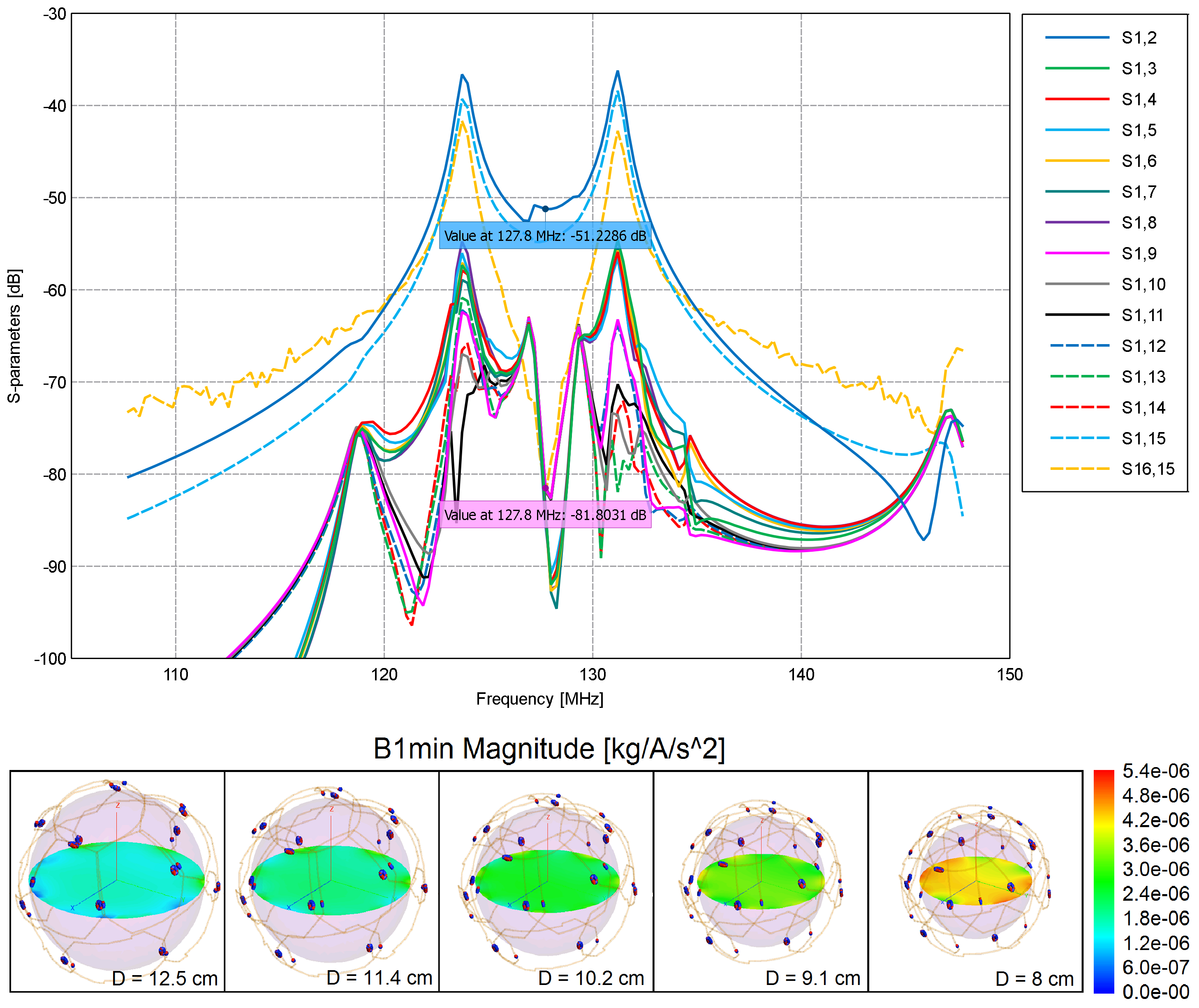
Simulations show an isolation between channels from -30 to -43 dB for the 10cm load (Fig. 2, top). These values decreased for the minimum (-26.8 to -30.7 dB) and maximum (-23.2 to -36.7dB) dimensions, since no adjustments were performed. B1- field maps (Fig. 2, bottom) show acceptable uniformity for all dimensions studied.
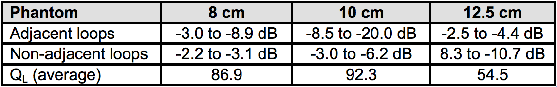
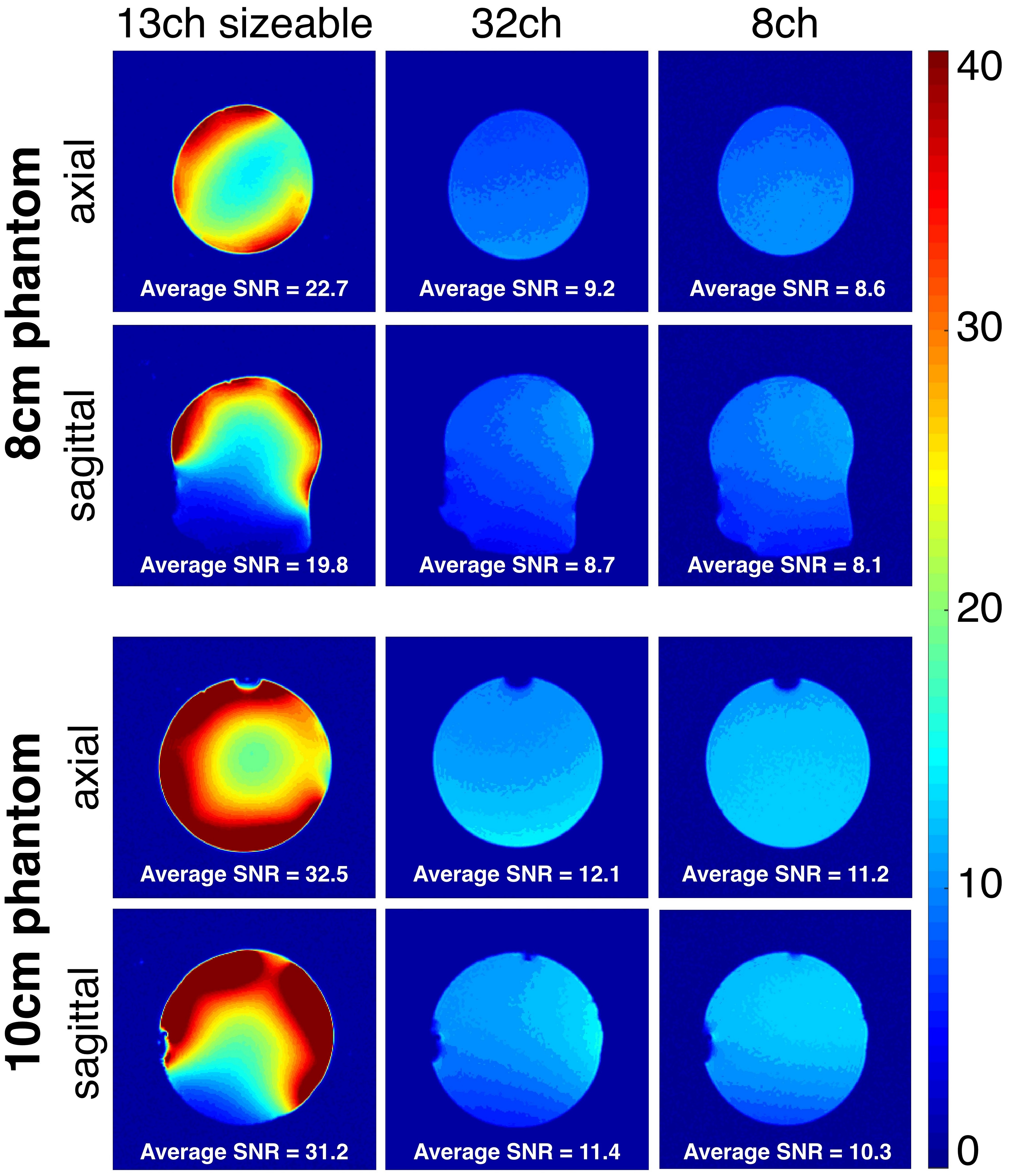
Decoupling between pairs of loops measured on the bench is shown in Table 1. Preamp decoupling in the range of -27 dB to -33 dB, largely compensated for the sub-optimal geometric decoupling found across adjustable sphere sizes. SNR maps computed from the acquired images are shown in Fig. 3.
Discussion
The overall isolation between channels (geometric plus preamp decoupling) obtained by simulations and bench tests suggested that a size adaptable array can be implemented. Images with higher SNR were obtained with the proposed coil due to the close proximity to different loads. The uniformity of the SNR patterns was affected mainly by mechanical design imperfections and asymmetries that increased the range of decoupling values. This can be improved by reducing the size of the elements and increasing the number of channels, which will also reduce the limits of the coupling range.Conclusions
The proposed approach resulted in an increased SNR compared to 8-Ch and 32-Ch commercial head coils, mainly in the cortex regions. The method can also help to restrict head motion if proper padding is used. It also could be considered for designs dedicated to other size-varying body parts, such as breast and limbs. The use of positive pressure and a safety system to protect the subjects can be included.Acknowledgements
We thank Fraser Robb, Miguel Navarro, Pei H. Chan, Jorge Guzman and Ken Bott from GE Healthcare for their valuable support. We also acknowledge Stephan Grimault from PERFORM Centre, where images were acquired. This work was funded by the Canada Research Chair in Quantitative Magnetic Resonance Imaging (JCA), the Canadian Institute of Health Research [CIHR FDN-143263], the Canada Foundation for Innovation [32454], the Fonds de Recherche du Québec - Santé [28826], the Fonds de Recherche du Québec - Nature et Technologies [2015-PR-182754], the Natural Sciences and Engineering Research Council of Canada [435897-2013] and the Quebec BioImaging Network.References
1. Taracila V, Navarro M, Gregan D, et al. Adaptive Head Array. ISMRM. 2014:4883.
2. Banerjee M, Follante C, Zemskov A, et al. Optimized Pediatric Suite with head array adjustable for patients 0-5 yrs of age. ISMRM. 2014:1768.
3. Keil B, Alagappan V, Mareyam A, et al. Size-optimized 32-channel brain arrays for 3 T pediatric imaging. MRM. 2011;66(6):1777-87.
4. Mareyam A, Xu D, Polimeni J, et al. Brain arrays for neonatal and premature neonatal imaging at 3T. ISMRM. 2013:4386.
Figures