1051
A Geometrically Adjustable Loop-Dipole (LD) Head Array for 10.5T1University of Minnesota, Center for Magnetic Resonance Research (CMRR), Minneapolis, MN, United States, 2University of Minnesota, Center for Magnetic Resonance Research (CMRR)
Synopsis
We designed a geometrically adjustable 16 channel transceiver head Loop-Dipole (LD) array which allowed for variation in element placement. Functionality was established without inter element decoupling circuitry. We simulated the resulting 16-channel LD array and compare to 8 channel dipole only and 8 channel loop only configurations. Finally we acquired in-vivo porcine images from a 10.5T whole-body imaging system to demonstrate principle functionality.
Evaluate possible performance advantages of 16-channel Loop-Dipole arrays for human head applications in a 10.5 T MR system.
Introduction
At ultra-high fields, multi-element transmit arrays with independent channels are essential to achieve acceptable B1 field homogeneity and to optimize transmit efficiency. Dipole elements combined with loop elements in particular configurations are predicted to yield optimal coil performance1-3. To investigate this, we compared an 8-channel dipole to a 16-channel loop-dipole (LD) array through simulation, built a head array and imaged a porcine head in vivo at 10.5T.
Methods
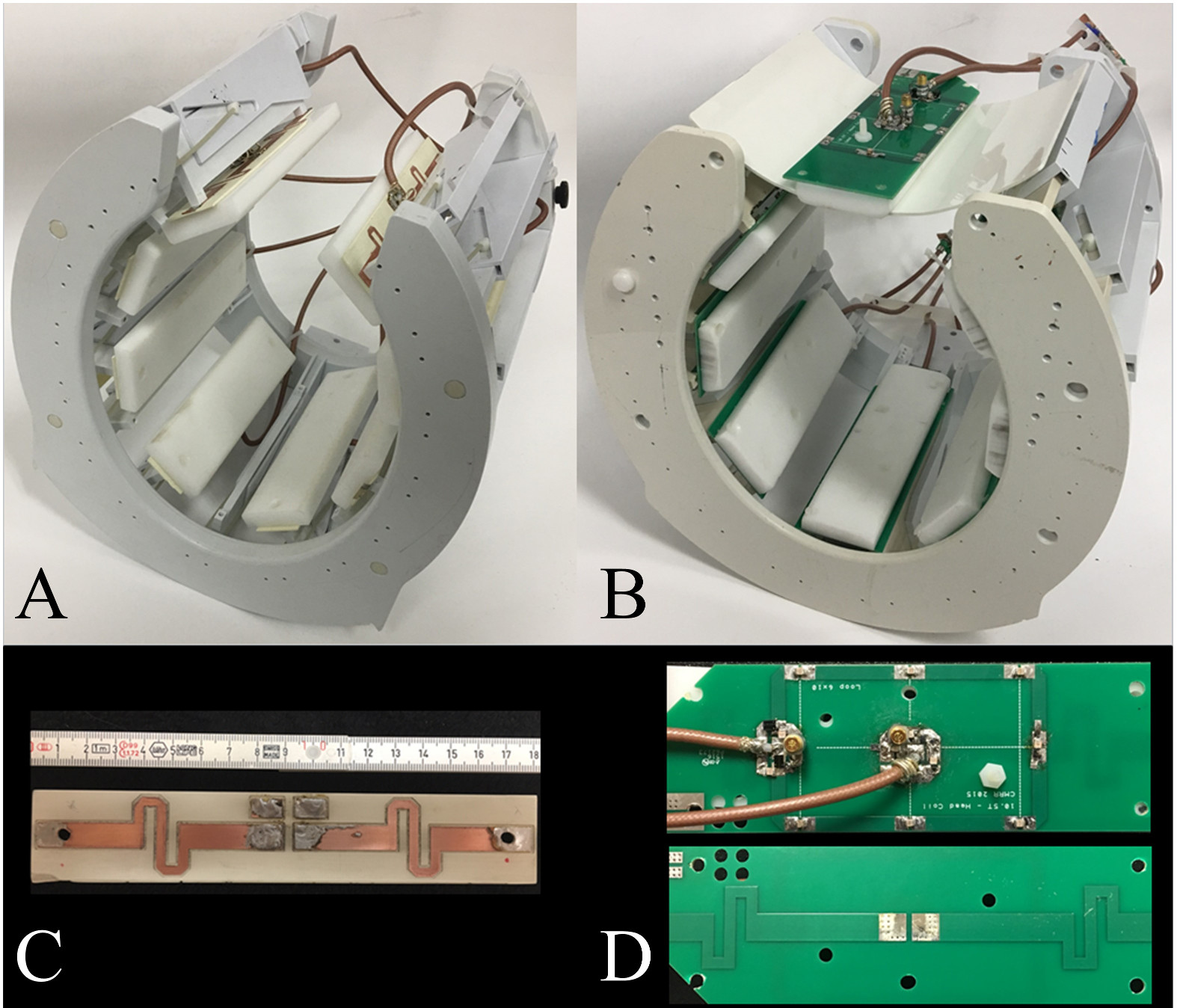
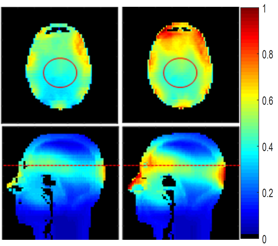
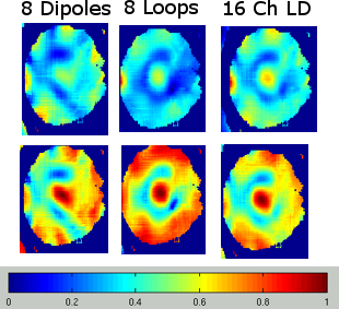
A geometrically adjustable coil element support frame was designed4 which allowed dipoles and dipole-loop elements to be mounted inside the 18 x 22 cm2 head support frame (Fig. 1). The mechanics of the frame allow for spatial readjustment of the individual dipole-loop elements by up to 2.5 cm radially. In each LD element, the loop and dipole are printed on opposite sides of the FR4 circuit board, with the loop positioned furthest from the patient. Total length of a fractionated dipole is 18 cm, and includes a capacitive L-matching network. The dimension of the loop is 6 x 10 cm2, and its matching is achieved with a lattice balun network. Teflon bars of 12 mm thickness on the patient side of each antenna element ensured a minimum distance between the subject and the dipole or LD conductor board. Computational electromagnetic simulation (XFdtd; REMCOM, State College, PA) was performed to calculate the B1+ field (Fig. 2). 16 channel LD and 8 channel dipoles were simulated when driven by independent voltage sources with identical amplitudes5. Each channel had a 45° phase shift in order to generate a uniform birdcage-like mode. A high-fidelity head model (Duke) that includes shoulders was selected for the geometry with a 2 x 2 x 2 mm3 resolution. Results were normalized to the maximum value of each individual plot based on a 90° pulse (2 ms). The performance of the sub-arrays of the LD array were compared in simulation by shimming a small central region of the brain and computing the fields using just the eight dipoles, just the eight loops, and the combined 16 elements that make up the LD array (Figure. 3).
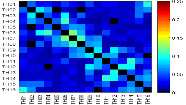
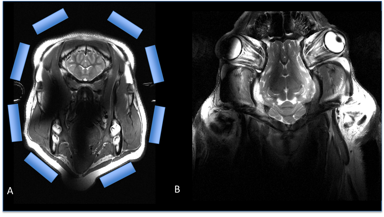
All data presented here were acquired with equal RF transmit power per channel with 16-channel Transmit/Receive interface (Virtumed LLC, Minneapolis, MN). The transmit phase increments for individual channels were adjusted for optimal image homogeneity in the porcine brain6. A close to human-sized pig was anesthetized according to our approved IACUC protocol and imaged as a surrogate for later human studies. The 10.5T / 88 cm whole-body magnet (Agilent, Santa Clara, CA) is combined with a whole-body gradient (SC72, Siemens Healthcare, Erlangen, DE) with 70 mT/m maximum amplitude and 200T/m/s maximum slew rate. The head of an anesthetized and ventilated 50 kg pig was loaded into the coil in prone position. For the experimental phantom imaging, actual flip angle imaging (AFI) sequence was used to measure transmit B1 profile and adjust the flip angle. The noise correlation matrix was obtained (Fig. 4). TSE images were collected with TR/TE = 5000/72 ms, 130° refocusing pulse, and an echo train length of 10 (Fig. 5).
Results and Discussion
The possibility to adjust spacing between antenna and sample is advantageous for dipoles and loops for consistent tune and match as well as better coupling to the sample and reduced radiation. Consistently good decoupling was observed, as indicated in Fig. 3, on the order of ~10-24 dB between neighboring elements for various geometries. We observed improved overall dipole decoupling with increased frequency - this allows for dipole spacing as close as 8 cm and follows Erturk’s observation for 447MHz body arrays7. Comparing the simulation data, overall B1+ of 16 channel LD is 20.3% higher than 8 channel dipole and at the center of the human brain the 16 channel LD shows on average 16.3% higher achievable B1+ than 8-channel dipoles. From AFI imaging, the transmit efficiency was 0.32 µT/sqrt (W) in the porcine brain. Finally, we obtained porcine images with both the 8-channel dipole and the 16-channel Loop Dipole coils. This is an acceptable initial arrangement of the elements for studying central brain slices on a human but does have drawbacks regarding a falloff towards the top of the brain. Future work will carefully evaluate alternative configurations which allow for better whole brain coverage.
Conclusion
We observed that a 16-channel Loop Dipole coil has potential advantages compared to an 8-channel dipole coils for both peripheral and central regions and will be a suitable candidate for human imaging of 10.5T MR imaging.
Acknowledgements
NIH-P41-EB015894, S10 RR029672, NIH-R01-EB006835, NIH-R01 EB007327References
1. Lattanzi, R. & Sodickson, D. K. Ideal current patterns yielding optimal signal-to-noise ratio and specific absorption rate in magnetic resonance imaging: computational methods and physical insights. (2012) Magn Reson Med 68, 286-304. 2. Wiggins, G.,etal.. Mixing loops and electric dipole antennas for increased sensitivity at 7 Tesla. p 2737.. (2013) Proceeding ISMRM, Salt Lake City, UT,USA, 2737. 3. Eryaman, Y.,et al. SAR reduction in 7T C-spine imaging using a "dark modes" transmit array strategy. (2015) Magn Reson Med 73, 1533-1539. 4. Adriany, G.etal. K. A geometrically adjustable 16-channel transmit/receive transmission line array for improved RF efficiency and parallel imaging performance at 7 Tesla. (2008) Magn Reson Med 59, 590-597. 5. Collins CM, Yang QX, Wang JH, et al. Different excitation and reception distributions with a single-loop transmit-receive surface coil near a head-sized spherical phantom at 300 MHz. (2002) Magn Reson Med 47,1026–1028. 6. Van de Moortele, etal. Fast Mapping of Relative B1+ Phase in the Human Head at 9.4 Tesla with a 14 Channel Transceive Coil Array. (2006) International Symposium on Biomedical Magnetic Resonance Imaging and Spectroscopy at Very High Fields 2006, Wuerzburg, Germany. 7. Erturk MA et.al Toward imaging the body at 10.5 tesla. (2016) Magn Reson Med doi : 10.1002/mrm.26487.Figures