1050
Plasma antennas in MRI: A four-channel transmit-receive plasma array at 3T1Experimental Physics 5, University of Wuerzburg, Würzburg, Germany, 2Magnetic Resonance and X-ray Imaging MRB, Developement Center X-ray Technology EZRT Fraunhofer Institute for Integrated Circuits IIS, Würzburg, Germany, 3C.J. Gorter Center for High Field MRI, Leiden University Medical Center, Leiden, Netherlands, 4Noras MRI products GmbH, Höchberg, Germany, 5Comprehensive Heart Failure Center (CHFC), University of Wuerzburg, Würzburg, Germany
Synopsis
In this work a new type of antenna array based on plasma columns was designed, and the feasibility of using such an array for both transmit and signal reception was investigated. A four-channel plasma antenna array for a 3T whole-body scanner was designed and constructed. Images were successfully acquired for the first time, and negligible mutual coupling of the individual array elements was observed. Both acquired signal-to-noise maps and the acquired images show a great potential, particularly due to the absence of mutual coupling of the individual array elements.
Purpose
Antennas based on plasmas rather than on metallic conductors represent a new concept in magnetic resonance imaging1 (MRI). Recently, the feasibility of plasma antennas were proposed for the transmit case1,2 . In this current work we present the first results from plasmas operating in transmit-receive mode. The design of a full-functional transmit-receive four-channel plasma antenna is presented and its feasibility for array imaging at 3T is demonstrated.Methods
A four-channel transmit-receive array was built for a 3T whole-body scanner. The inner diameter of the array was 260 mm and the usable length was 530 mm. Coaxial wave launchers3 were used to couple the transmitter and the receiver to the plasma as shown in figure 1. A custom-built transmit-receive switch, power splitters and appropriate phase shifters were used for the array setup. No additional decoupling mechanism of the individual elements of the array was used. Signal-to-noise (SNR) maps were acquired with a single channel, the four-channel array and the body coil by imaging 20 consecutive gradient echo images with TR=50 ms, TE=1.29 ms, matrix size 64 x 64, slice thickness 10 mm and a field-of-view (FOV) of 306 x 306 mm. The imaging capability of the plasma array was shown by acquiring a 2D gradient echo image with TR=74 ms, TE=2.87 ms, 32 averages, matrix size 230 x 256, slice thickness 7 mm and a field-of-view of 200 x 200 mm for sagittal images and 155 x 155 mm for transversal images.Results
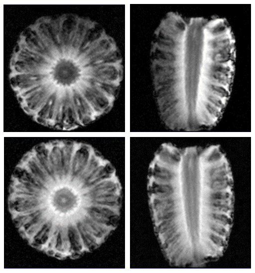
The measured SNR maps are shown in figure 2. The SNR distribution of a single channel is highest close to the plasma, and falls off with the distance as expected. The four-channel setup shows good coverage of the center of the phantom, no coupling between the individual elements was seen, and homogeneous coverage was achieved using the expected quadrature phase shifts. The SNR of the body coil is approximately six times higher than that of the plasma, which confirms previous results1 that showed that conventional light-tubes are distinctly sub-optimal in terms of MR performance. An image of a pineapple acquired with a single plasma antenna and a four-channel plasma array in transmit-receive mode is shown in figure 3. The single channel setup shows the expected drop-off in SNR with distance from the antenna. The four-channel setup shows homogeneous coverage within the sample with no visible artifacts of mutual coupling.Discussion
This work has shown for the first time that it is possible to use plasmas as receive antennas without any additional necessary electronic circuits. It has also been shown that these antennas can be combined to arrays without any special decoupling mechanism. Currently this approach is not as effective as conventional metal-based coils, and requires improvements in the efficiency of the wave launcher and power transfer into the plasma. As outlined in the original work1 the main reason for the low SNR is the fast rapid of the plasma after the transmit pulse which ignites the plasma. In future setups we aim to investigate mechanisms to sustain the plasma during reception. As the plasma column itself is not a resonant tuned device, the same plasma array can be used in principle for other frequencies as well by an adapted wave launcher, especially for high field MRI or multi-nuclei experiments.Conclusion
It has been shown for the first time that antennas based on plasma can be used for MRI as transmit-receive devices and antenna arrays. The absence of mutual coupling between individual elements allows easy integration into a variety of different array geometries. Additionally it offers great potential for high field MRI and multi-nuclei experiments.Acknowledgements
No acknowledgement found.References
1. Webb, A.G. and Aussenhofer, S.A. 2015. Evaluation of plasma-based transmit coils for magnetic resonance. Journal of Magnetic Resonance. 261, (Dec. 2015), 49-53.
2. Moisan, M., Shivarova, A. and Trivelpiece, A.W. 1982. Experimental investigations of the propagation of surface waves along a plasma column. Plasma Phys. 24, 11 (Nov. 1982), 1331-1400.
3. Carlile, R.N. 1964. A Backward-Wave Surface Mode in a Plasma Waveguide. J. Appl. Phys. 35, 5 (1964), 1384.
Figures