1049
Improved uniformity of the spatial PSF for portable MRI using an optimized rotating magnet1A.A. Martinos Center for Biomedical Imaging, Massachusettts General Hospital, Charlestown, MA, United States, 2Harvard Medical School, Boston, MA, United States, 3EECS, Massachusetts Institute of Technology, Cambridge, MA, United States
Synopsis
The development of a low-cost portable MRI scanner for brain imaging could facilitate imaging in new sites with insufficient space, power, or funding for traditional scanners. To address this need, we previously established a 3D encoding method using a rotating inhomogeneous B0 field and RF phase gradients, but uncontrolled field patterns showed encoding problems near the object center. Here we show this problem can be fixed in an optimized 122 kg head-sized permanent magnet with a built-in approximately linear encoding field in 2D images with improved resolution homogeneity across the field of view.
Purpose
Development of a portable low-cost MRI scanner for human brain imaging.Methods
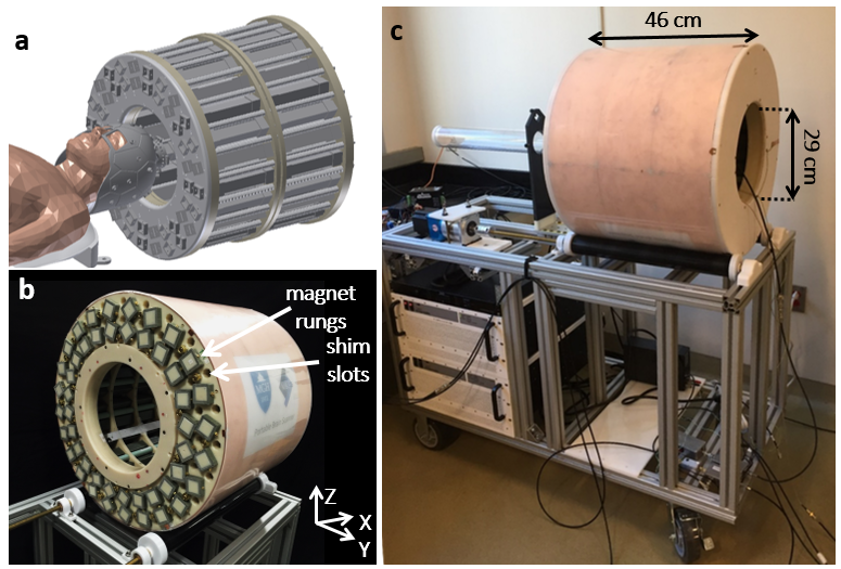
A prototype portable brain MRI scanner using a rotating Halbach permanent magnet was previously reported [1]. In this system, the built-in Spatial Encoding Magnetic fields (SEMs) are used to do generalized projection imaging in the Y-Z plane. Transmit Array Spatial Encoding (TRASE) was demonstrated for encoding the data along the magnet’s cylindrical axis of rotation, X [2,3]. Images produced by the prototype scanner contain significant blurring in the center where a spatial minimum in the SEM (gradient null) aligned with the axis of rotation. The addition of a significant 1st order field component to the inherent field variation of a Halbach magnet improves resolution uniformity. In response, an optimization method was described to design a rotating Halbach magnet without this null using the Genetic Algorithm to generate possible magnet designs to be populated with discrete N42 or N52 NdFeB cubes or plastic gap [4]. The objective of the optimization was to generate magnet designs within the geometrical constraints for human imaging that contain a significant 1st order (gradient) field component with controlled over-all residual field variation. Figure 1a shows a CAD model of the magnet housing with patient, receive helmet, and patient support. To construct the magnet array, the full magnet former was assembled with ABS rings that hold 1” square fiberglass tubes, which are rotated to form the dipole mode of a Halbach array (Fig. 1b). Each tube is then populated with magnet cubes using a pushing jig. Slots for additional shim magnets were included but not populated. A copper shield was wrapped around the magnet and connected to copper-lined covers at the magnet ends to reduce RF interference and shield the RF transmit coil. The total weight of the constructed magnet is 122 kg. A aluminum cart with stepper-motor-controlled rollers was constructed (Fig. 1c) to allow the scanner to be easily transported and couple to a similar patient table design (not shown). A 3D SEM field map was acquired using a 3-axis gaussmeter (MetroLabs) mounted to a 3-dimension robotic translation stage. Images were obtained from a 10cm diameter, ~1cm thick 2D resolution phantom.Results
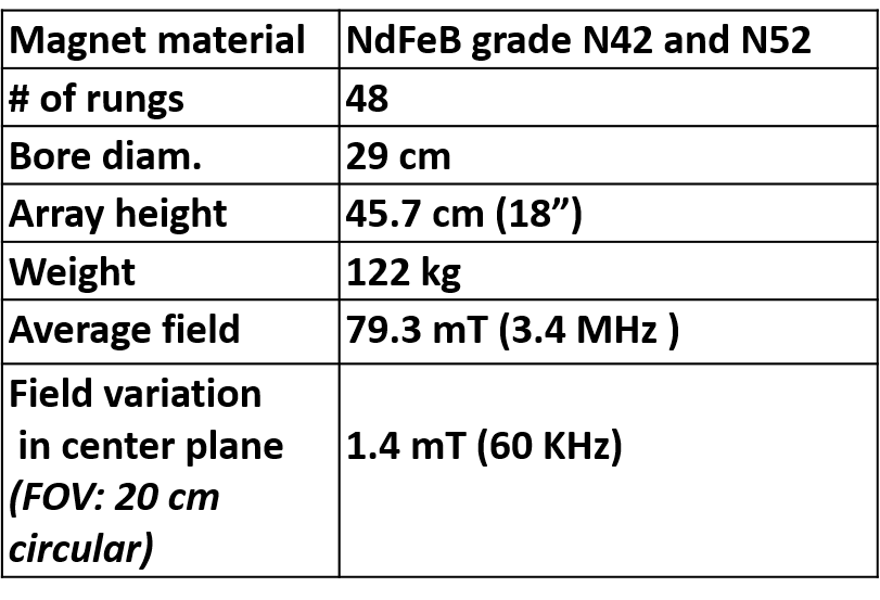
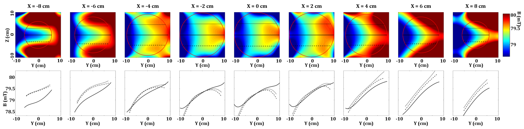
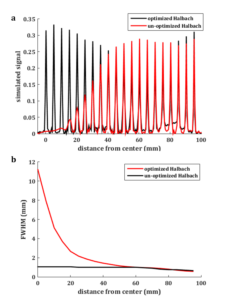
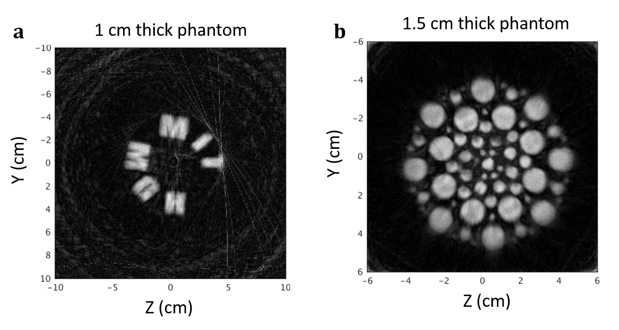
Table 1 outlines the properties of the optimized head size magnet. The measured field maps in Figure 2 show a significant 1st order field component in the Y direction. Figure 3a shows 1D simulated images of point sources along the radius of the 20cm VOI using the measured field map from the center slice SEM, as well as the measured SEM of the previously used un-optimized Halbach magnet. Figure 3b shows the width of the resulting point-spread functions. The measured fields were in good agreement with the simulation. Figure 4 shows resulting 2D images of 3D printed phantoms positioned at isocenter. Figure 4a was acquired from 72 magnet rotations spaced 5 degrees apart (acquisition time 15 min.), and Figure 4b was acquired from 181 magnet rotations spaced 2 degrees apart (acquisition time 38 min.).Discussion
The consistency of the spatial resolution across the FOV is greatly improved due to the dominant 1st order field component. The improvement in resolution uniformity is most dramatically seen at the center of the image, where previously the image was severely blurred [1] and we can now crisply resolve 3mm circles (Fig. 4b). Remaining challenges of the complete human scale brain scanner include: (1) design of efficient high-bandwidth RF coils and RF pulses for uniform excitation in the VOI, (2) incorporation of TRASE for encoding along the X dimension. To optimize SNR and provide additional spatial encoding, we also plan to design a 24-channel array of receive loops on a close-fitting helmet. The array will have PIN-diode detuning and preamplifier decoupling, extending these methods to the low field imaging regime.Conclusion
We have shown that the spatial “encoding hole” of rotating permanent magnets can be fixed in a human-size low-cost and light-weight magnet suitable for brain MRI. This scanner utilizes a previous described unconventional MRI architecture [1], which eliminates the need for a homogeneous B0 magnet and gradient coils offering significant ancillary hardware (GPAs and water cooling) reductions.Acknowledgements
The authors thank Elfar Adalsteinsson, Cristen Lapierre, Bastien Guerin, Laleh Golestani Rad. Support by NIH R01EB018976.References
(1) Cooley CZ, Stockmann JP, Rosen MS, Wald LL, et al. Two-dimensional imaging in a lightweight portable MRI scanner without gradient coils. Magn Reson Med. 2015 Feb;73(2):872-83.
(2) Cooley CZ, Stockmann JP, Rosen MS, Wald LL, et al. 3D Imaging in a Portable MRI Scanner using Rotating Spatial Encoding Magnetic Fields and Transmit array spatial encoding (TRASE). In Proc. of the ISMRM, Toronto, Canada, 2015, page 0703.
(3) Sharp JC, King SB. MRI using radiofrequency magnetic field phase gradients. Magn Reson Med. 2010 Jan;63(1):151-61.
(4) Cooley CZ, Haskell M, Wald LL, et al. Portable Magnet Design Optimization for Brain Imaging without Gradient Coils. In Proc. of the ISMRM, Singapore, 2016, page 3556.
Figures