1048
Ratio-adjustable power splitters for array-compressed parallel transmission and RF shimming1Institute of Imaging Science, Vanderbilt University, Nashville, TN, United States, 2Department of Radiology and Radiological Sciences, Vanderbilt University, Nashville, TN, United States, 3Department of Biomedical Engineering, Vanderbilt University, Nashville, TN, United States
Synopsis
Introduction
Array-compressed parallel transmission was recently proposed as a way to reduce the number of RF power amplifiers required for many-coil parallel transmission1,2. This is achieved by connecting a large number of coils to a small number of channels via an array compression network that implements optimized coil-to-channel combinations using power splitters, attenuators and phase shifters. Previous array compression networks used tunable attenuators comprising a Wilkinson power splitter connected to a Wilkinson power combiner via unequal transmission line lengths, but this resulted in significant (approximately 60%) power dissipation in the network2. Here we propose novel ratio-adjustable power splitters (RAPS), which perform the combined duties of power splitting and attenuating, and will enable array compression networks with minimal power loss. The splitters could also be useful for RF shimming3-8 with a single amplifier, with the ability to tune the shims by adjusting transmission line lengths.Methods
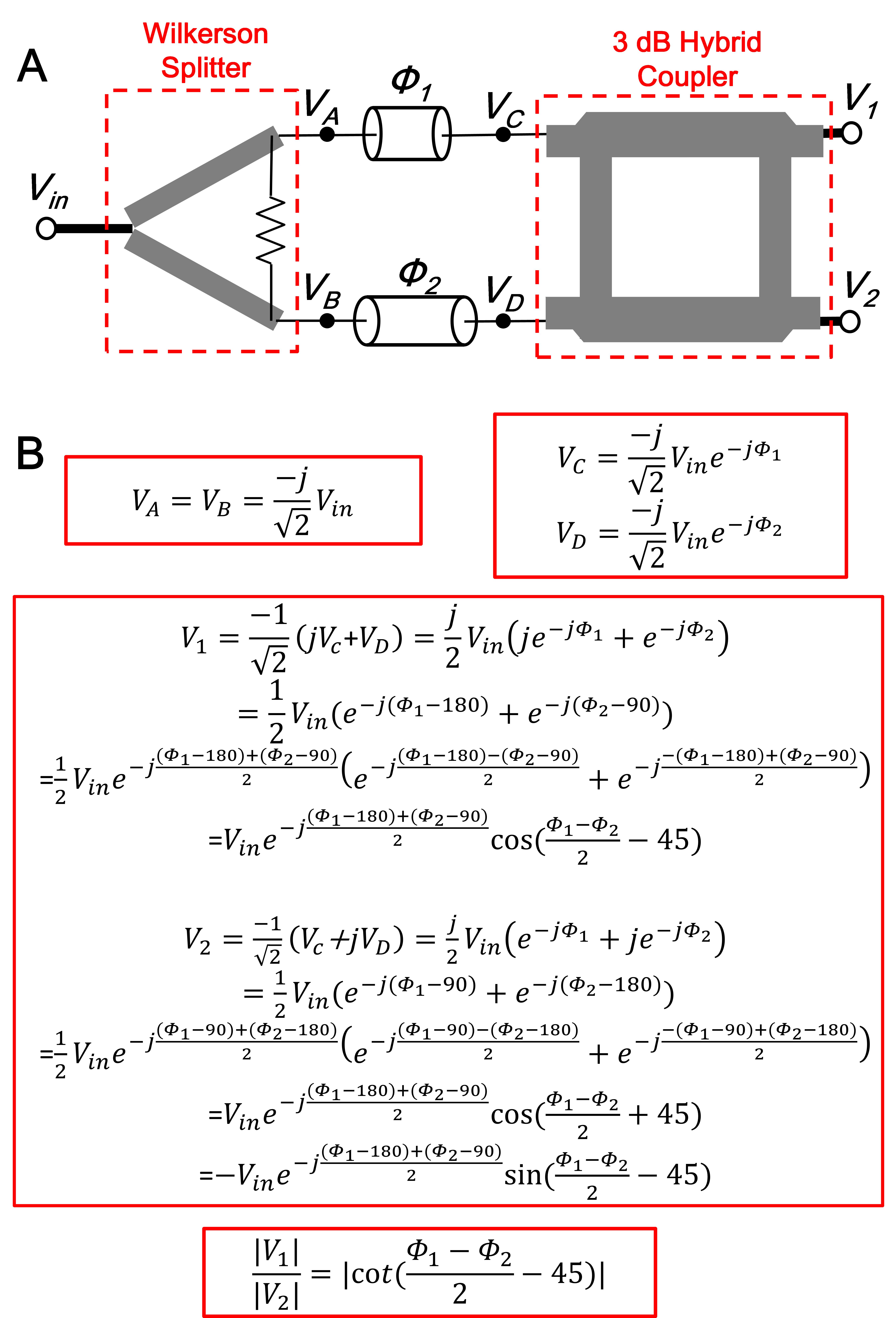
Fig.1A shows the ratio-adjustable power splitter (RAPS) comprising a Wilkinson splitter and a hybrid coupler connected by two transmission lines of different lengths, which induce phase shifts of Φ1 and Φ2. The amplitude relationship between the two output ports is derived in Fig.1B as: $$|V_1 |⁄|V_2 |=|co t((Φ_1-Φ_2)⁄2-45)| [1]$$ $$ V_1^2+V_2^2=V_{in}^2 [2]$$
Eq.1 indicates that the output ratio has a $$$cot$$$ dependence on the difference between the transmission line lengths, and can thus be tuned by adjusting those lengths. Eq.2 indicates that it is a lossless network where the sum of output power always equals the input power.
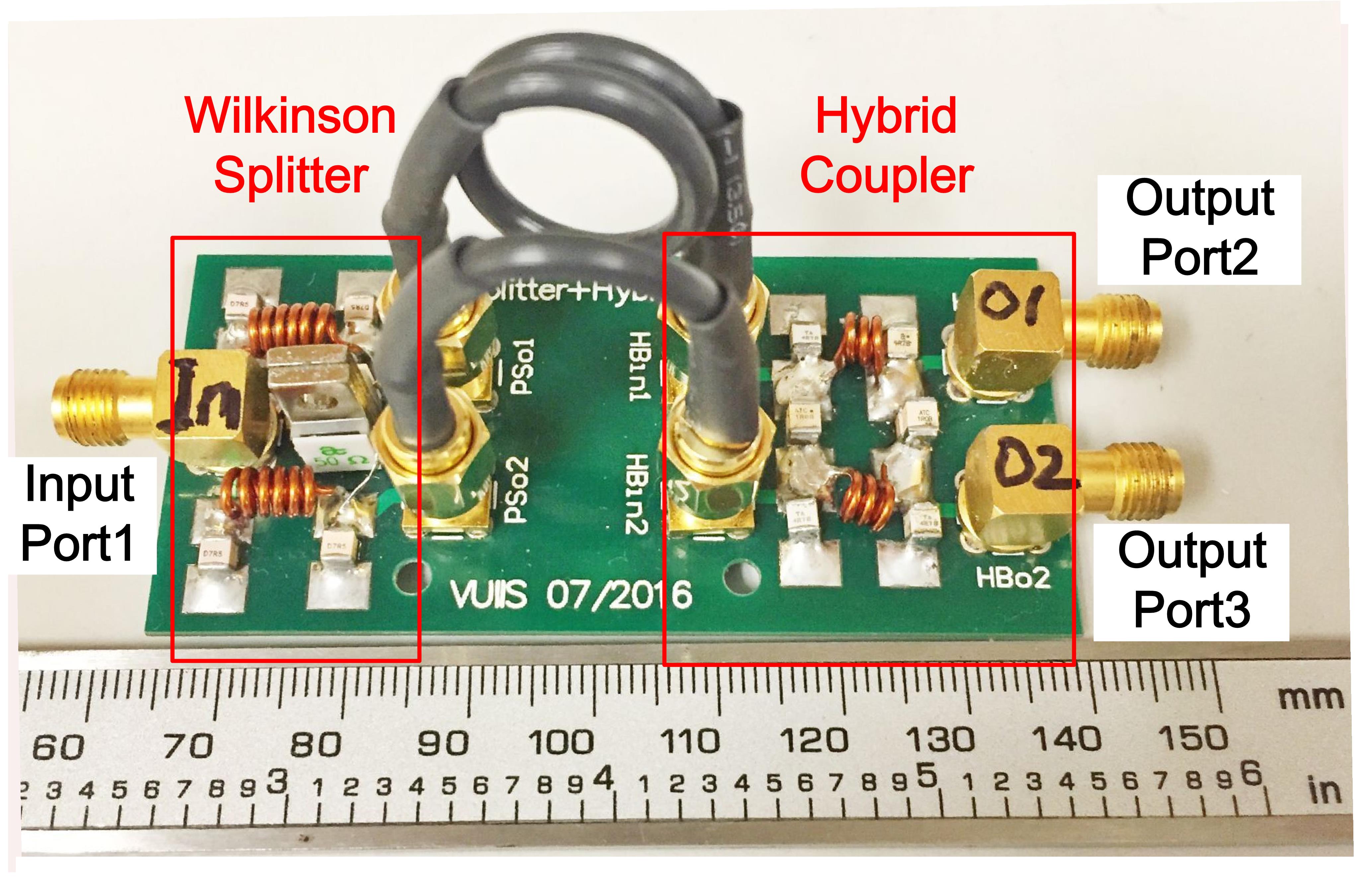
Fig. 2 shows a fabricated RAPS made on PCB with dimensions 3x7 cm2. Two cables (one fixed and one variable) are used to change the relative phase shifts of the split signals and consequently the ratio between the output voltage amplitudes. A library of cable lengths was populated to achieve output ratios from 0 dB to 7 dB in steps of 1 dB. Bench measurements were performed with a network analyzer, and MR experiments were performed on a 7T whole-body scanner (Philips Healthcare, Best, Netherlands). In the MR experiments, a RAPS was inserted between the RF amplifier and a birdcage head coil (Nova Medical, Wilmington, MA). Axial B1+ maps were then acquired in a 15 cm phantom using the DREAM method9, across the range of output ratios.
Results
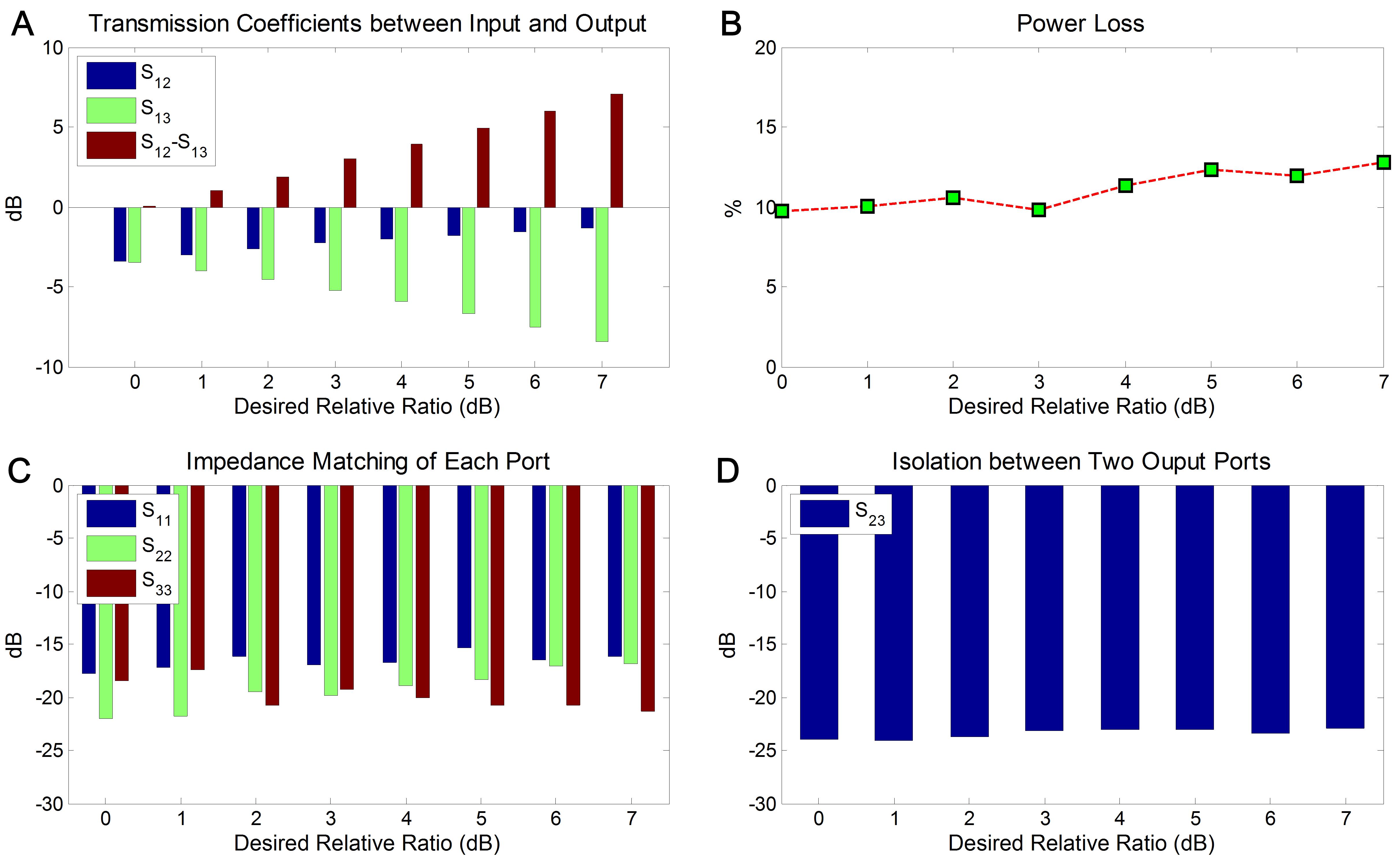
Fig. 3 shows S-parameter results from the bench tests with target ratios from 0 dB (equal splitting) to 7 dB. The RF signal was input to port 1, and output from ports 2 and 3. The deviations between measured and desired ratios between outputs (S12-S13) are less than 0.05 dB (Fig. 3A). The total power loss is approximately 10% (~0.5 dB) at each ratio (Fig. 3B). Fig. 3C shows the matching performance of each port and Fig. 4D shows the isolation between the two output ports, in which acceptable matching (<-16 dB) and excellent isolation (<-22 dB) was achieved across ratios.
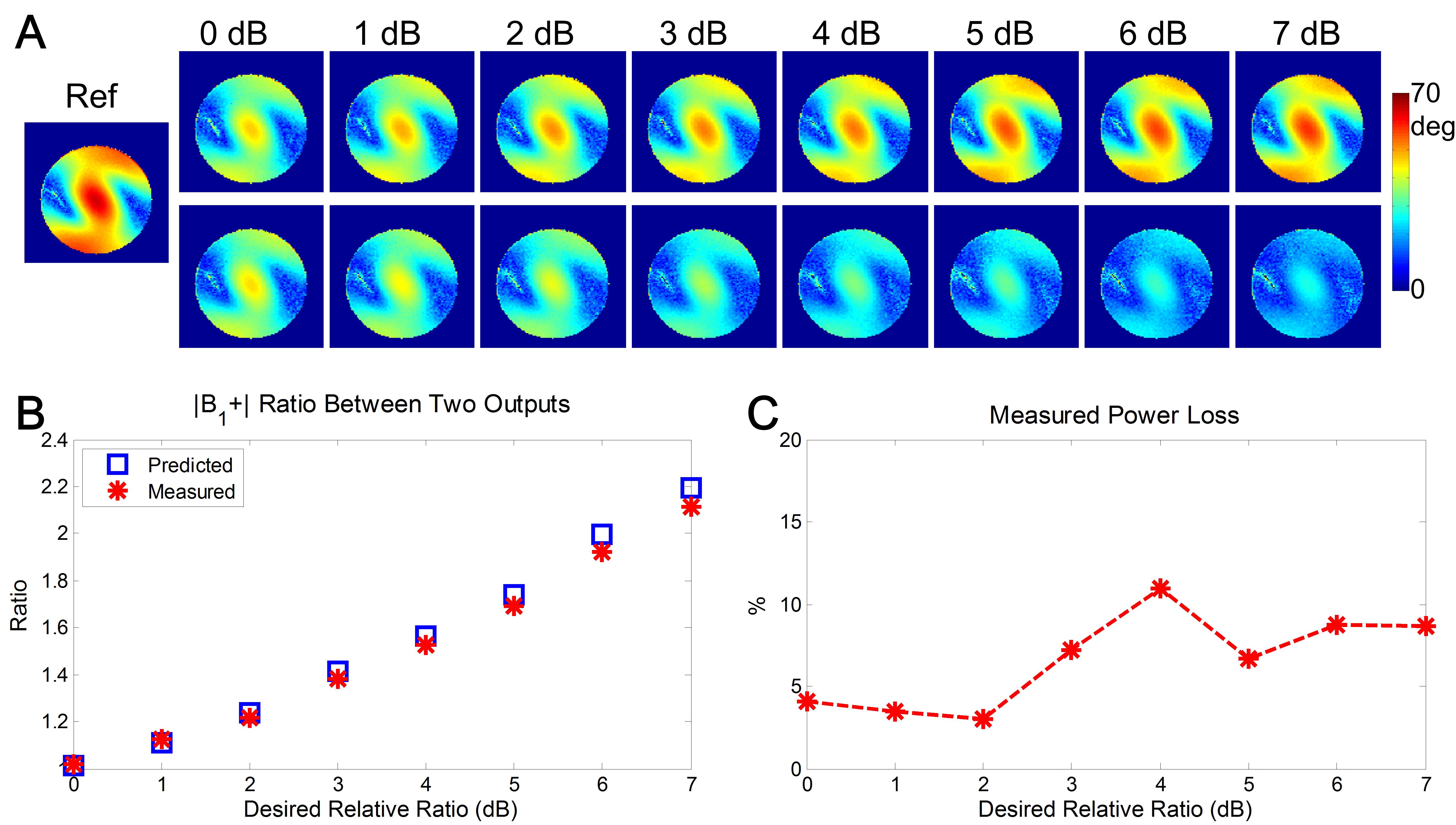
Fig. 4A shows normalized B1+ maps measured using splitters of different ratios. Fig. 4B plots predicted (using S-parameter measurements) and measured average B1+ at each ratio. The measured and predicted ratios match well, with errors less than 4%. Fig. 4C shows calculated power loss based on the measured average B1+. As expected from the bench measurements, the power loss was low (<12%), which means that >94% of the B1+ magnitude was maintained.
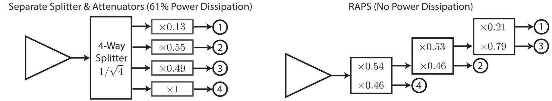
Fig. 5 compares array compression network topologies for the accelerated spiral parallel pulse design of Ref. 2. The networks implement the same relative coil weightings, but the RAPS-based network is lossless, while the topology from Ref. 2 dissipates 61% of the input power (neglecting insertion loss in both cases).
Discussions and Conclusion
Wilkinson splitters or hybrid couplers can be directly designed for desired output ratios (either equal or unequal), however, their ratios are dependent on branch-lines’ impedances which are not readily adjustable in practice. MR imaging results showed that the performance of RAPS’s will not be influenced by the static or gradient magnetic fields even when placed close to RF coils, which could be attributed to their compact dimensions and non-magnetic components. The RAPS circuit is lossless and has little power dissipation, and thus incurs negligible temperature rise during scans. In conclusion, we developed a ratio-adjustable power splitter which can handle high RF power and is almost lossless. The device can be used to implement tunable array-compressed parallel transmission and RF shimming networks with minimal power loss.Acknowledgements
This work was supported by NIH R01 EB 016695 and NIH R21 EB 018521.References
1. Cao, Z., Yan, X. and Grissom, W. A. (2016), Array-compressed parallel transmit pulse design. Magn Reson Med, 76: 1158–1169. doi: 10.1002/mrm.26020
2. Yan, X., Cao, Z. and Grissom, W. A. (2016), Experimental implementation of array-compressed parallel transmission at 7 Tesla. Magn Reson Med, 75: 2545–2552. doi: 10.1002/mrm.26239
3. Mao, W., Smith, M. B. and Collins, C. M. (2006), Exploring the limits of RF shimming for high-field MRI of the human head. Magn Reson Med, 56: 918–922. doi: 10.1002/mrm.21013
4. Van den Bergen, B., van den Berg, C. A.T., Klomp, D. W.J. and Lagendijk, J. J.W. (2009), SAR and power implications of different RF shimming strategies in the pelvis for 7T MRI. J. Magn. Reson. Imaging, 30: 194–202. doi: 10.1002/jmri.21806
5. Deniz, C. M., Brown, R., Lattanzi, R., Alon, L., Sodickson, D. K. and Zhu, Y. (2013), Maximum efficiency radiofrequency shimming: Theory and initial application for hip imaging at 7 tesla. Magn Reson Med, 69: 1379–1388. doi: 10.1002/mrm.24377
6. Adriany G, Van de Moortele PF, Wiesinger F, Moeller S, Strupp JP, Andersen P, Snyder C, Zhang X, Chen W, Pruessmann KP, Boesiger P, Vaughan T, Ugurbil K: Transmit and receive transmission line arrays for 7 Tesla parallel imaging. Magn Reson Med. 2005; 53(2):434-45. PubMed PMID: 15678527
7. Shajan, G., Hoffmann, J., Budde, J., Adriany, G., Ugurbil, K. and Pohmann, R. (2011), Design and evaluation of an RF front-end for 9.4 T human MRI. Magn Reson Med, 66: 594–602. doi: 10.1002/mrm.22808
8. Hoffmann, J., Shajan, G., Scheffler, K. et al. Numerical and experimental evaluation of RF shimming in the human brain at 9.4 T using a dual-row transmit array. Magn Reson Mater Phy (2014) 27: 373. doi:10.1007/s10334-013-0419-y
9. Nehrke, K. and Börnert, P. (2012), DREAM—a novel approach for robust, ultrafast, multislice B1 mapping. Magn Reson Med, 68: 1517–1526. doi: 10.1002/mrm.24158
Figures