1047
In vivo MRI with Concurrent Excitation and Acquisition using Dynamic Analog Cancellation with Real-time Feedback1Deptartment of Radiology, Medical Physics, Medical Center – University of Freiburg, Freiburg, Germany, 2Institute of Microstructure Technology, Karlsruhe Institute of Technology, Karlsruhe, Germany, 3Department of Electrical and Electronics Engineering, Bilkent University, Ankara, Turkey
Synopsis
In this work concurrent excitation and acquisition (CEA) was realized in a clinical MRI system using a fully automated analog cancellation unit to suppress the unwanted transmit signal leakage during acquisition. The cancellation circuit is composed of a voltage-controlled phase shifter and attenuator, which changes phase and amplitude of a small copy of the transmit signal with a real-time feedback from MRI system. 90 dB on-resonant isolation was achieved within 2 s, where an isolation threshold was set to trigger re-adjustment of decoupling parameters when coil loading changes. To demonstrate feasibility, CEA MR data of a phantom and in vivo wrist were acquired.
Introduction
The isolation of Tx and Rx channels in concurrent excitation and acquisition (CEA) MRI is a problem similar to full-duplex telecommunication. In CEA MRI, Tx and Rx are present simultaneously and they use the same frequency, so that In-band full-duplex (IBFD) techniques must be used to separate the Tx from the Rx signal. IBFD methods use either passive or active suppression, or digital cancellation [1]–[3]. Following a similar approach in [3], very high amounts of on-resonant decoupling is required to implement CEA MRI [4], which was successfully demonstrated in in vivo CEA MRI[5],[6].
In this work we present a decoupling system that benefits from all decoupling concepts of IBFD: passive suppression using geometrical decoupling, active cancellation using an analog cancellation circuit, and digital cancellation. The analog cancellation system was equipped with a real-time feedback control to automatize the decoupling procedure to be able to adapt the CEA system to variable loading conditions of the RF system.
Methods
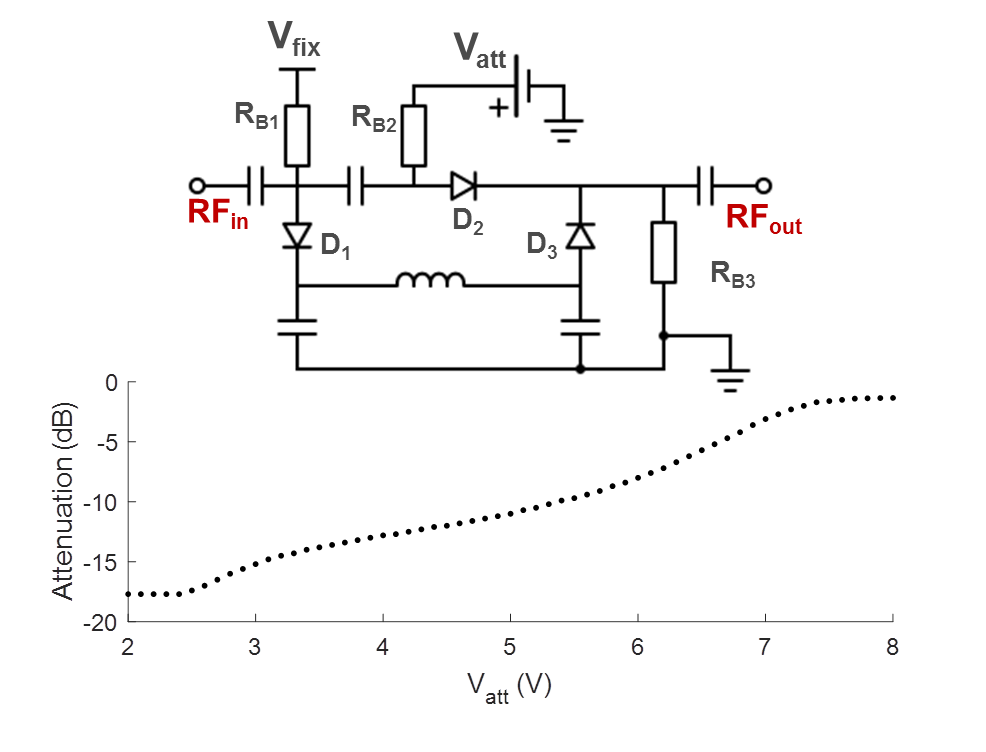
CEA with active analog cancellation and real time feedback was implemented in a clinical 3T MRI system (Siemens, Erlangen). The setup of the total system is shown in Fig.1. To keep Tx noise low, a custom-made LNA with 30mW output was used. Tx (ø=15cm) and Rx coils (ø=12cm) were placed orthogonally for geometric decoupling (Fig.1). A pick-up loop coil (PUC) was used to independently measure the Tx waveform. For leakage suppression a voltage-controlled phase shifter (Fig.2) and attenuator (Fig.3) were used to provide a cancellation signal, which was added to the Rx signal before amplification. Control voltages were continuously updated in a real-time feedback loop.
An external PC was used to implement real-time feedback control. To adjust the voltages of the phase shifter and the attenuator, raw data were acquired with a calibration sequence that consists of a constant rectangular RF pulse and concurrent data acquisition. Raw data from each repetition was sent directly from the MRI receiver system to the external PC. A control script was then changing the phase and amplitude settings of the analog cancellation circuit via a USB interface which controlled output voltages of the digital power supply. The calibration sequence was repeated until the transmit leakage was below a user-defined threshold.
To demonstrate the performance of the analog cancellation system, the coils were loaded with a human hand, and the volunteer was asked to change the position during the calibration procedure. For CEA imaging, a 3D radial CEA sequence with silent gradients [6] was applied (Fig.5). As the initial values for DC voltages of the attenuator and the phase shifter, values from the phantom setting were used. In vivo CEA images are compared to a high resolution GRE image as an anatomical reference (Fig.5)
Results and Discussion
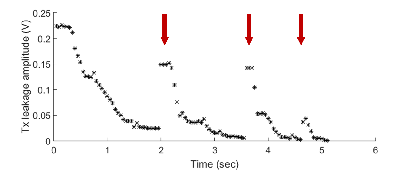
For the automated decoupling performance, initial decoupling took 40 iterations or 2s to converge. Subsequently, fewer iterations were required to re-adjust the parameters after the position of the hand was changed intentionally (Fig.4, arrows). The performance was not affected when the threshold was lowered from 78dB to 89dB on-resonant isolation.
Fig.5 shows coronal slices of 3D data of the human wrist acquired with CEA and GRE. The wrist bones have higher intensity with CEA, and extensor finger tendons, which are not represented in the GRE image, provide a higher signal intensity in CEA. Carpal bones have also a higher signal in CEA image, even in trabecular bone. Overall contrast to noise is higher in GRE due to intrinsic T2* weighting.
The analog cancellation system proposed in this work provides a suppression of the leakage signal of about 62dB, which is consistent with cancellation values found in full-duplex radio communication[2]. The combination of geometric decoupling[7] and the analog cancellation system always achieved an isolation of 89±2dB, which was also used as a stopping criterion for the automatic feedback system. In clinical MRI systems this suppression is not sufficient, and thus additional digital subtraction during post-processing was necessary to achieve the required total isolation of 100dB[8]. To minimize quantization errors, however, analog cancellation must be higher.
During CEA, maximum deviation of less than 10% from the receive noise floor was measured, which indicates the effect of the Tx-noise.
CEA MRI with dynamic analog cancellation is an initial step to bring this method into the clinical practice. First, it is time efficient due to the automated feedback decoupling operation; second, reduction in decoupling due to motion or changes in loading can be compensated in short time. CEA is a promising approach in MRI due to the advantages of 100% acquisition efficiency and extremely low peak RF powers.
Acknowledgements
DFG grants HA 7006/1-1 and BO 3025/8-1 are gratefully acknowledged.References
[1] A. Sahai, G. Patel, C. Dick, and A. Sabharwal, “On the impact of phase noise on active cancelation in wireless full-duplex,” IEEE Trans. Veh. Technol., vol. 62, no. 9, pp. 4494–4510, 2013.
[2] M. Duarte, C. Dick, and A. Sabharwal, “Experiment-driven characterization of full-duplex wireless systems,” IEEE Trans. Wirel. Commun., vol. 11, no. 12, pp. 4296–4307, 2012.
[3] D. Bharadia, E. McMilin, and S. Katti, “Full duplex radios,” SIGCOMM ’13 Proc. ACM SIGCOMM 2013 Conf. SIGCOMM, vol. 43, no. 4, pp. 375–386, 2013.
[4] M. Salim, A. C. Özen, M. Bock, and E. Atalar, “Detection of MR Signal during RF Excitation using Full-Duplex Radio System,” in 24th Scientific Meeting, International Society of Magnetic Resonance in Medicine, 2016, p. 3636.
[5] S.-M. Sohn, J. T. Vaughan, R. L. Lagore, M. Garwood, and D. Idiyatullin, “In vivo MR imaging with simultaneous RF transmission and reception,” Magn. Reson. Med., vol. 0, pp. 1–7, Sep. 2016.
[6] A. C. Özen, E. Atalar, J. Korvink, and M. Bock, “In vivo Concurrent Excitation and Acquisition MRI with Self-referenced Active Decoupling,” in 24th Scientific Meeting, International Society of Magnetic Resonance in Medicine, 2016, p. 2179.
[7] F. Bloch, W. W. Hansen, “The Nuclear Induction Experiment,” Phys. Rev., vol. 70, pp. 474–489, 1946.
[8] A. C. Özen, M. Bock, and E. Atalar, “Active decoupling of RF coils using a transmit array system,” Magn. Reson. Mater. Physics, Biol. Med., 2015.
Figures