0970
Dynamic permanent magnet array for ultra-low field magnetic resonance imaging1University of Queensland, St Lucia, Australia
Synopsis
Conventional MRI scanners rely on superconducting magnets making them heavy and expensive and putting MRI beyond the reach of much of the world’s population. Ultra-low field (ULF) MRI instruments offer the possibility of novel image contrast mechanisms, are less costly and are potentially portable, enabling use in unconventional situations. This project addresses ULF-MRI’s biggest challenge, low signal-to-noise ratio, by using the novel approach of dynamic, mechanically-operated small permanent magnet arrays to generate the magnetic fields required for prepolarisation and spatial encoding.
INTRODUCTION
Magnetic resonance imaging (MRI) with its superior soft tissue contrast has supplant other imaging modalities for many disorders. To achieve their high sensitivity, conventional MRI scanners rely on strong magnetic fields (>1 Tesla) produced by cryogenically cooled superconducting magnets. Hence, these instruments are heavy and exceptionally expensive to purchase, operate and maintain, limiting their use to major research or clinical facilities and putting MRI beyond the reach of much of the world’s population. In light of these drawbacks, MRI instruments operating at ultra-low field (ULF) strengths (<0.01 T) that do not require superconducting magnets have raised considerable interest [1-3]. In addition to being less costly and potentially portable, such instruments also offer the possibility of new applications. However, the biggest challenge for ULF-MRI is low signal-to-noise ratio (SNR), a consequence of weaker sample magnetisation, which degrades image resolution and prolongs image acquisition times. Current methods in ULF research to increase SNR like sample pre-polarisation or implementation of high-sensitive magnetometers are sub-optimal since resistive coil technology interfere with magnetometers, have high power consumption and lead to sample heating due to energy dissipation [3-5]. We introduce a dynamic, mechanically-operated permanent magnet arrays (PMAs), based on Halbach technology, to obviate resistive coil technology for ULF magnetic field generation [6]. With these magnet arrays, stronger fields without current flow can be generated which should lead to SNR increase, compared to resistive coils. Moreover power consumption and eddy current effects, which can lead to signal degradation, artefacts and additional noise are reduced.METHODS
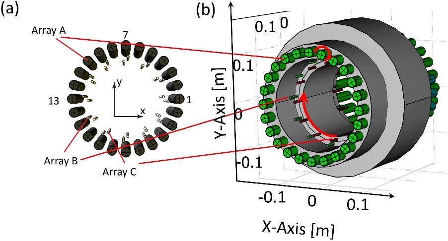
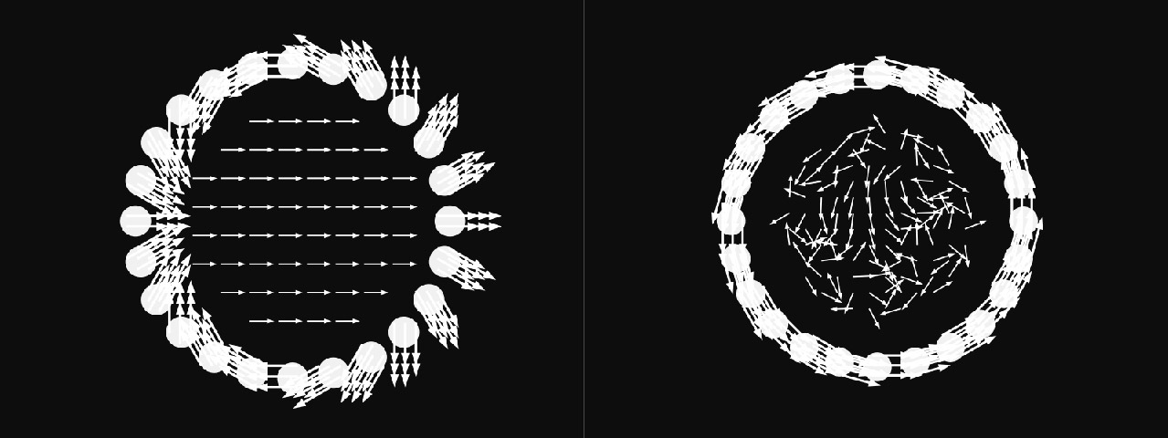
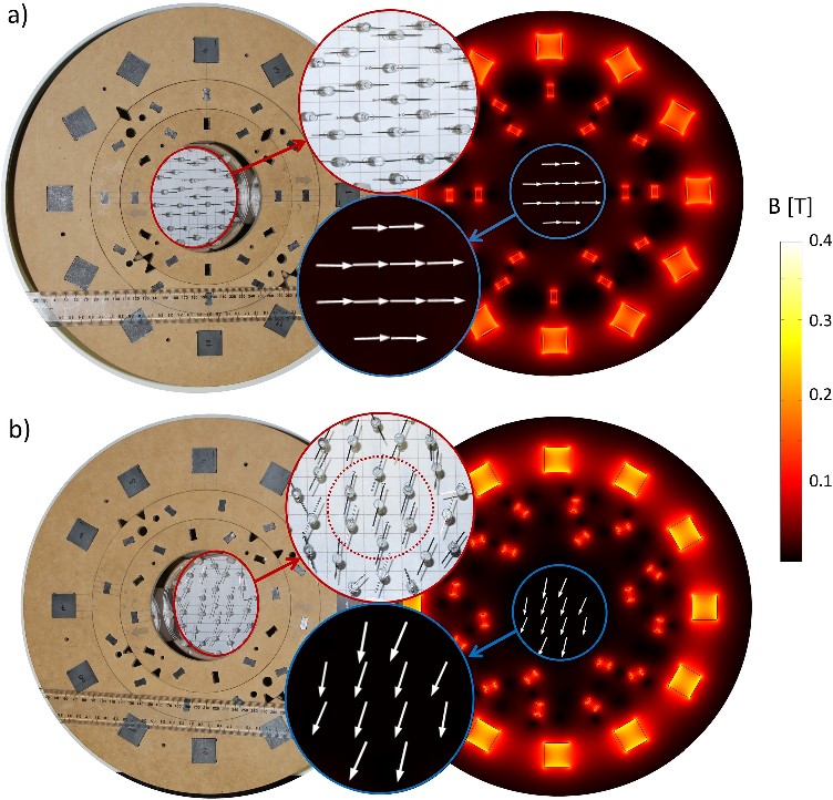
We employed the finite element method using COMSOL© (Fig 1). The permanent magnets are arranged to form a Halbach (Fig 2, left) or tangential magnetisation pattern (Fig. 2, right), to generate the pre-polarisation, Bp, and measurement field Bm. We evaluated for this configuration achievable magnetic field strength, homogeneity, switching time and magnetic forces. A manually operated prototype was simulated and constructed to validate the numerical approach and to verify the generated magnetic field (Fig 5).RESULTS
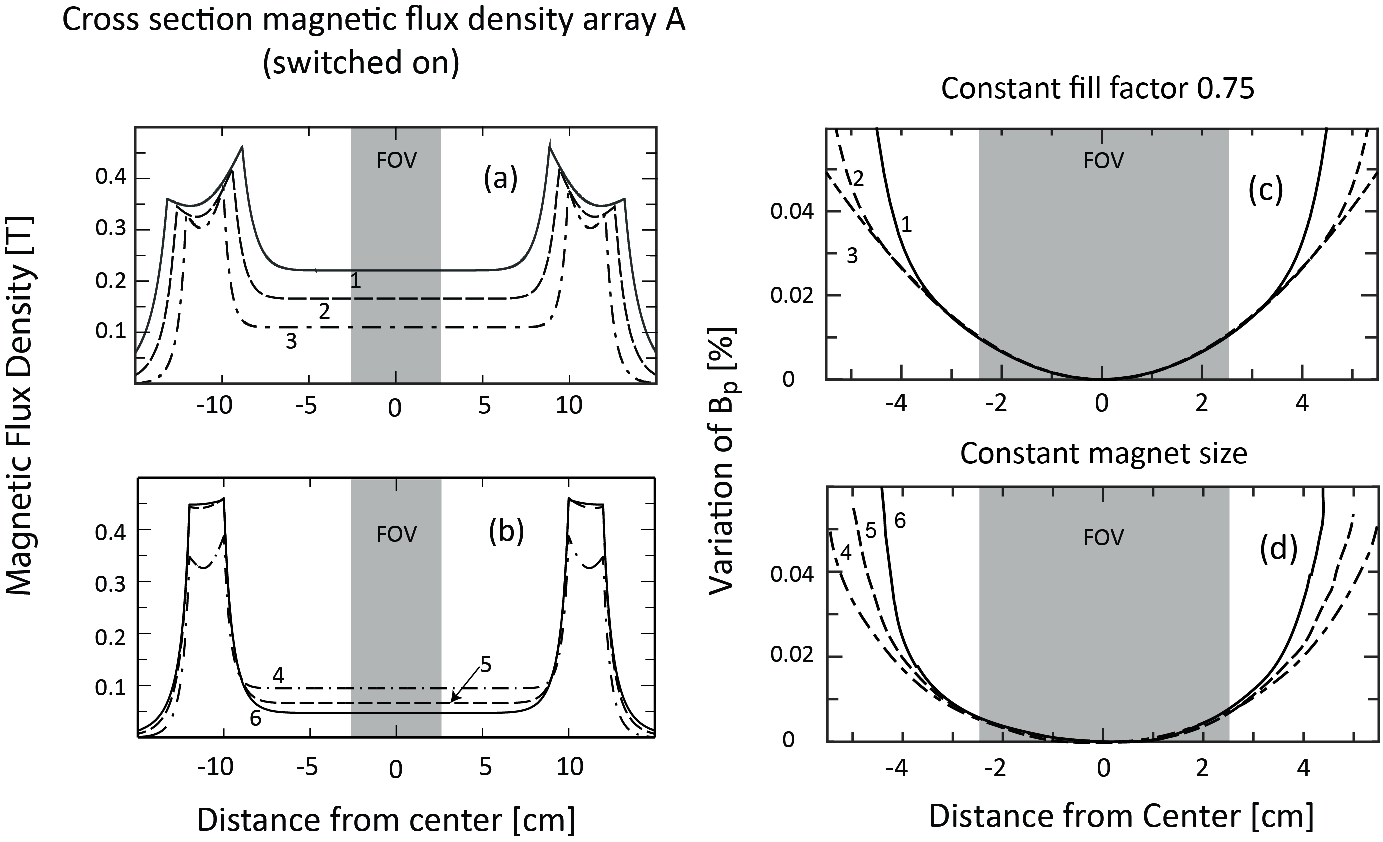
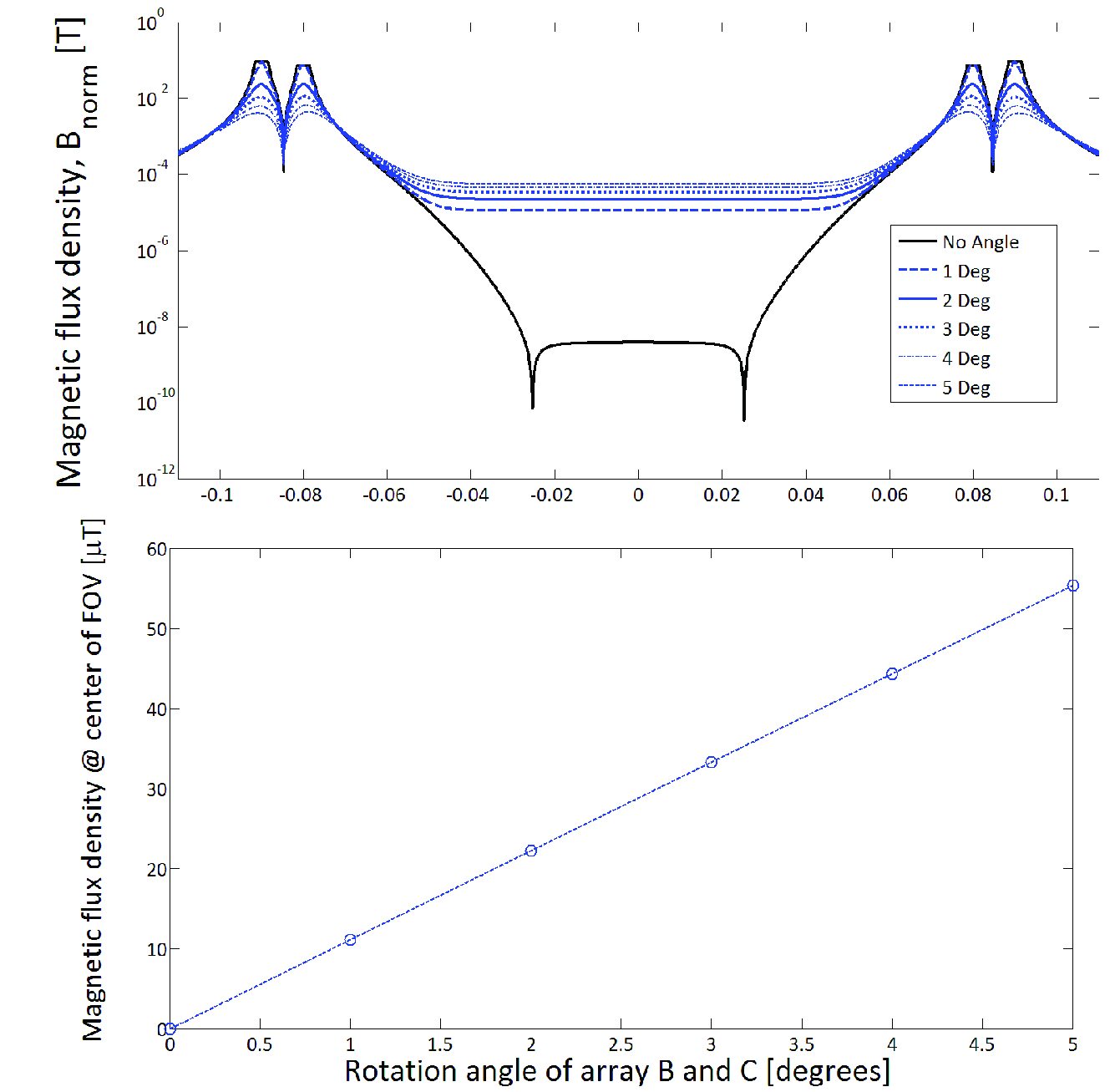
Our simulation predicted strong Bp magnitudes above 100 mT, higher than presently achieved in ULF instruments using resistive coil technology (Fig 3a,b). The magnetic field inhomogeneity for Bp is less than 0.03% (300 ppm) within a field of view of 5 x 5 x 5 cm3 (Fig 3c,d). Variable measurement fields ranging from near zero to 50 μT were generated by small rotations of two concentric cylindrical Halbach arrays B and C (Fig 4a, b) with the outer array A in the tangential pattern (Fig 2b). Nominal magnitude deviations were below 0.02% or 200 ppm without shimming (Fig 4c). Switching off Bp rapidly is crucial and can be achieved by the use of high-quality actuators. Our model predicted fast switching times (within 6 ms) from the pre-polarisation to the measurement state comparable to current ULF instruments using resistive coils and customized switch boxes.DISCUSSION
Our results show that the magnetic fields for ULF-NMR relaxometry experiments can be generated by prescribed rotations of individual magnets or the arrays. Achieved pre-polarisation field strength Bp and homogeneity can provide a significant increase in SNR compared to coil based ULF instrumentation. We showed that pre-polarization field cancellation can be achieved in less than 10ms and energy consumption is significantly reduced. We demonstrated that two concentric permanent magnet arrays (Array B and C) can generate the measurement field Bm, with the magnitude controlled by mutual rotations. This allows to perform ULF relaxometry at different frequencies, for instance, to explore different contrast mechanisms. The constructed PMA prototype (Fig 5) demonstrates the ability to generate varying magnetic fields and the validity of the numerical approach. The modular PMA design allows additional magnet arrays to be added, for instance, to generate non-linear gradient fields employed for spatial encoding in ULF-MRI.CONCLUSION
Our proposed permanent magnet array for ULF-MRI differs substantially from the resistive coil-based configuration reported in the literature. We demonstrated for ULF-NMR that strong pre-polarisation and highly homogeneous measurement fields are generated by a combination of rotation of individual permanent magnets and rotation of Halbach arrays. This obviates resistive coil technology for magnetic field generation and lead to significant reduction of energy consumption. With the implementation of novel high sensitive coil-based magnetometers, currently developed in our group, our findings may benefit future developments in ULF-NMR/MRI increasing the potential for compact, low energy, portable instrumentation operating under ambient conditions.Acknowledgements
M. W. Vogel is financially supported by the Australian Research Council Discovery Early Career Research Award No. DE140100229. D. C. Reutens is supported by the Australian National Health and Medical Research Council (https://www.nhmrc.gov.au/) program grant No. 628952 and No. 631352. Parts of this project are supported by the Bill & Melinda Gates Foundation (www.gatesfoundation.org/) OPP1007237.References
1. Sarracanie M, LaPierre CD, Salameh N, Waddington DEJ, Witzel T, Rosen MS. Low-Cost High- Performance MRI. Scientific Reports. 2015;5:15177. doi: 10.1038/srep15177.
2. Cooley CZ, Stockmann JP, Armstrong BD, Sarracanie M, Lev MH, Rosen MS, et al. Two- dimensional imaging in a lightweight portable MRI scanner without gradient coils. Magn Reson Med 2015;73(2):872-83.
3. Kraus Jr RH, Espy M, Magnelind P, Volegov P. Ultra-Low Field Nuclear Magnetic Resonance: A New MRI Regime: Oxford University Press; 2014.
4. Espy M, Matlashov A, Volegov P. SQUID-detected ultra-low field MRI. J Magn Reson 2013; 228 (0): 1-15.
5. Vogel MW, Vegh V, Reutens DC. Numerical study of ultra-low field nuclear magnetic resonance relaxometry utilizing a single axis magnetometer for signal detection. Med Phys. 2013; 40(5) 052301.
6. Vogel MW, Giorni A, Vegh V, Reutens DC. Ultra-low field nuclear magnetic resonance relaxometry with a small permanent magnet array: A design study. PLoS One. 2016;11(6).
Figures