0969
The Design and Implementation of a 64 Channel Arbitrary Gradient Waveform Controller1MRRC Yale University, New Haven, CT, United States
Synopsis
Generating additional magnetic fields independently from the MR scanner’s hardware requires additional controllers, current amplifiers and DC coils. Here we present the design and implementation of a 64 channel arbitrary gradient waveform controller that can be used to drive current amplifiers with analog inputs. We describe the controller’s architecture and how sequences are developed. We will also discuss the important criteria needed to synchronize the waveforms with the MR scanner. Finally, we will show the completed controller and the first MR result.
Introduction
There has been a recent interest in developing magnetic field shapes independent of the MR scanner’s gradient and shim coils (1-5). This interest has been for shimming, both static and dynamic, as well as linear and non-linear encoding. What all applications have in common is the need for a method of defining and generating arbitrary waveforms synchronous with the MR scanner. The requirements for the controller are identical to the gradient controllers on the MR scanner but many more channels are needed. The requirements include a simple and fast method of defining and downloading the waveforms to a controller; each channel has to be synchronous with both the MR sequence and each other and finally have the ability to drive a whole range of current amplifiers. Here we present the complete design and implementation of a modular 64 channel gradient waveform controller. We show both electrical and MR results and discuss possible future system implementations.Method
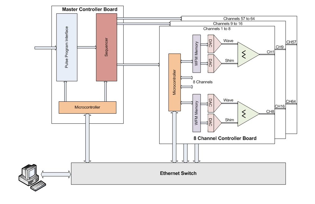
Figure 1 shows a block diagram of the system. A master controller interfaces with the main MR scanner and defines the timing for itself and up to eight waveform boards. It is important that a common clock is used on all boards and that they are all synchronized to the master controller. Each waveform board contains eight independent channels which have their own memory (8MB per channel), digital to analog convertor and a summation amplifier so a shim offset can be applied independently from the waveform sequence. Sequences are developed on a PC using either the graphical user interface (GUI) or a simple text file and downloaded ahead of the sequence via a fast Ethernet protocol. Waveforms can be defined in two different ways: Firstly, a Dynamic Shim Updating (DSU) mode which only generates trapezoids. Sequences are defined as a series of “events”. The user only has to define each event’s amplitude and a global ramp time is automatically added. This has the advantage of requiring much less memory and communication time. Each event is played out upon the receipt of a trigger pulse from the scanner’s pulse program and will loop back to the beginning after a user defined number of events. Secondly, a full arbitrary waveform mode. A sequence is built from a number of waveform blocks defined on a 4us grid. Special commands are used so that delays and periods between shapes do not have to be defined on the grid, thereby reducing memory and communication requirements. A sequence is initiated with a single trigger pulse from the pulse program. The sequence can be resynchronized with a pulse from the pulse program during each TR to prevent any synchronization errors occurring during long sequences.Results
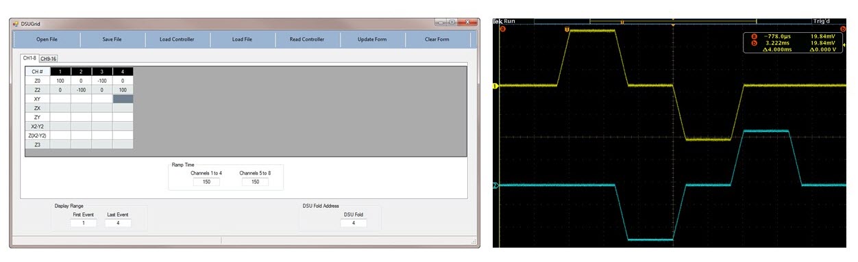
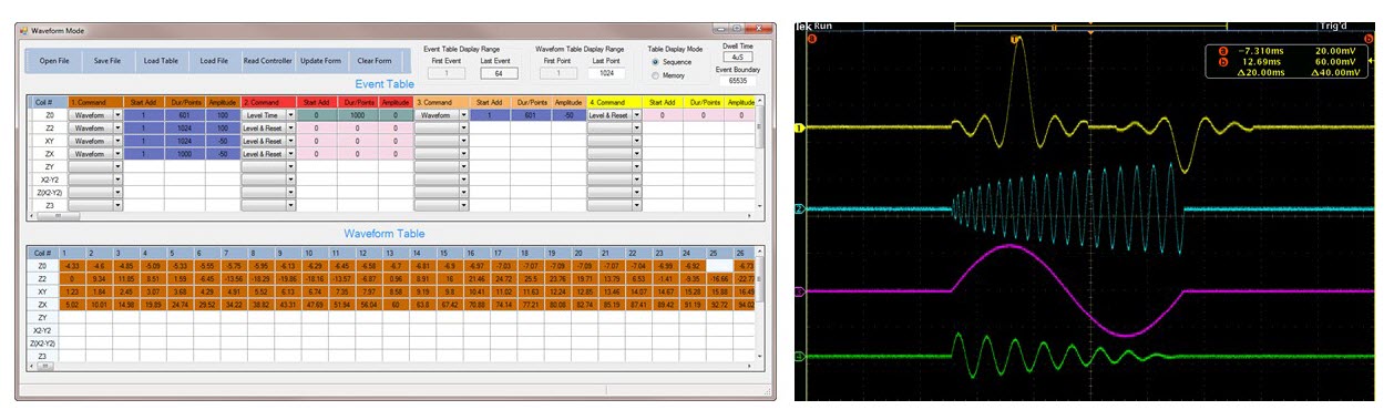
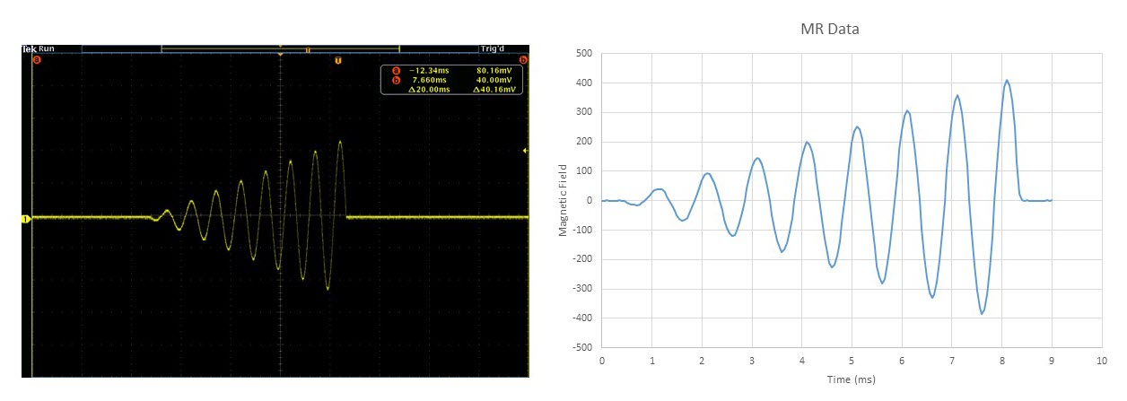
Figure 2 shows two channels in DSU mode playing out a simple four event sequence. The GUI is used to edit the sequence and then download it to the controller. Each of the events has a ramp time of 150us added to it. Four trigger pulses are needed to implement this sequence. Figure 3 shows a more complex arbitrary waveform sequence output and its GUI. Only a single trigger pulse is needed to initiate the sequence. The first channel (yellow trace) contains two waveforms separate by a delay. The two waveforms are defined only once in memory but the second waveform’s amplitude is halved and inverted. The other channels each contain a single waveform. Figure 4 shows an output waveform and the magnetic field output generated by a single DC coil out of a 48-multi-coil setup (6). The MR data was acquired from a small 8 uL volume placed adjacent to the DC coil and measured as the phase difference between signals acquired in the absence and presence of the input waveform. The high fidelity and accuracy of the experimental waveform is apparent.Discussion
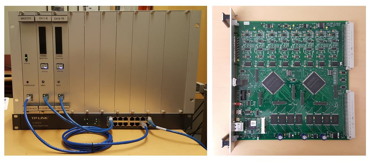
A multi-channel gradient waveform controller has been developed for the purpose of driving current amplifiers to generate magnetic fields within a MR experiment. Figure 5 shows a complete 16 channel controller. The unit is modular and can support up to 64 channels per controller. Multiple controllers can be “daisy chained” together to add even more channels which are all synchronized to the MR scanner using trigger pulses from the scanner’s pulse program. The individual channel outputs can be connected to any set of current amplifiers that have an analog input. This has been shown to work here with a simple 1A multi-coil current amplifier. The unit will also be used to drive 100A gradient amplifiers for non-linear encoding experiments.Acknowledgements
No acknowledgement found.References
1. Hennig J, Welz AM, Schultz G, Korvink J, Liu Z, Speck O, Zaitsev M. Parallel imaging in non-bijective, curvilinear magnetic field gradients: a concept study. Magma 2008;21:5-14.
2. Stockmann JP, Ciris PA, Galiana G, Tam L, Constable RT. O-space imaging: Highly efficient parallel imaging using second-order nonlinear fields as encoding gradients with no phase encoding. Magn Reson Med 2010;64:447-456.
3. Juchem C, Nixon TW, McIntyre S, Boer VO, Rothman DL, de Graaf RA. Dynamic multi-coil shimming of the human brain at 7T. J Magn Reson 2011;212:280-288.
4. Juchem C, Umesh Rudrapatna S, Nixon TW, de Graaf RA. Dynamic multi-coil technique (DYNAMITE) shimming for echo-planar imaging of the human brain at 7 Tesla. Neuroimage 2015;105:462-472.
5. Stockmann JP, Witzel T, Keil B, Polimeni JR, Mareyam A, LaPierre C, Setsompop K, Wald LL. A 32-channel combined RF and B0 shim array for 3T brain imaging. Magn Reson Med 2016;75:441-451.
6. Juchem C, Herman P, Sanganahalli BG, Brown PB, McIntyre S, Nixon TW, Green D, Hyder F, de Graaf RA. DYNAmic Multi-coIl TEchnique (DYNAMITE) shimming of the rat brain at 11.7 T. NMR Biomed 2014;27:897-906.
Figures