0968
Monolithic Transmit Line Resonator as a Combined B1/B0-shim Coil Element1The Richard M. Lucas Center for Imaging, Radiology Department, Stanford University, Stanford, CA, United States, 2The Richard M. Lucas Center for Imaging, Electrical Engineering Department, Stanford University, Stanford, CA, United States, 3A. A. Martinos Center for Biomedical Imaging, Massachusetts General Hospital, Charlestown, MA, United States
Synopsis
In this work we propose and evaluate, for the first time, the use of a single-turn-single-gap Transmit Line Resonator as a combined RF-transceive and B0-shim element. We compare this design to a standard loop in terms of both RF and B0-shimming performance. The benefits of our combined TLR/B0-shim design are improved RF performance due to the fixed and smaller number of lumped elements, and the increase in B0-shim efficiency. Our results show the TLR element design to be an ideal building block for high-channel-count integrated Parallel Reception, Excitation and Shimming (iPRES) arrays.
Purpose
Monolithic Transmission Line Resonators (TLR) consist of overlapping gapped conductor strips on the two sides of a low-loss dielectric substrate. By varying parameters such as trace width, substrate thickness and permittivity, number of gaps and number of turns per layer, it is possible to build a distributed capacitance resonant structure. The TLR design has been shown to be a good choice for the construction of RF coil arrays1-3. In this work we propose and evaluate, for the first time, the use of a single-turn-single-gap TLR as a combined RF-transceive and B0-shim element. We compare this design to a standard loop4,5 in terms of both RF and B0-shimming performance. The benefits of our combined TLR/B0-shim design are improved RF performance due to the fixed (independent of loop size) and smaller number of lumped elements, and 2x increase in B0-shim efficiency. Our results show the TLR element design to be an ideal building block for high-channel-count integrated Parallel Reception, Excitation and Shimming (iPRES) arrays5.Methods
A single-element TLR was built on a 3.175mm thick Rogers RO5880 substrate. As shown in Figure 1, we chose a rectangular TLR shape with outer dimensions of 40mm x 75mm. For these dimensions, using TLR theory3 augmented by numerical simulations (FEKO, Altair), we found that the TLR self-resonance could be tuned to 298MHz using a strip width of 2.5mm. Three lumped-element capacitors (Johanson Technology EIA1111) were used for matching, fine tuning and DC block (CM=20 pF, CT=4.7pF, Cblock=300pF). Three RF-chokes (Coilcraft 132-20SM, L=538 nH, Z=1kΩ@300MHz) were added to the circuit to allow shim current to flow. A single drive point was used for both RF and shim currents, reducing cable interactions compared to other designs4. Three more coils were built for experimental comparisons: a second TLR coil without chokes and DC block, and two simple loops with 4 capacitors per loop (3xCT=6.8pF, CM=27 pF), with and without chokes, as shown in Figure 2. All coils were matched and tuned to 298MHz with better than -15dB reflection coefficient. Unloaded and loaded Q factors (QU and QL, respectively) were measured in S12 using a dual-decoupled probe and a Keysight ENA E-5080A VNA. Scanner measurements were performed on a GE Discovery MR950 7T scanner. In order to evaluate the efficiency of the four coils in generating B1 and B0 fields, Bloch-Siegert B1+ and multi-TE B0 mapping was performed on all coils with and without DC current. A 32-channel array with 4 rows of 8 elements each was simulated via Method of Moments (FEKO) to study B1 performance and via Biot-Savart formula to study B0 performance.Results
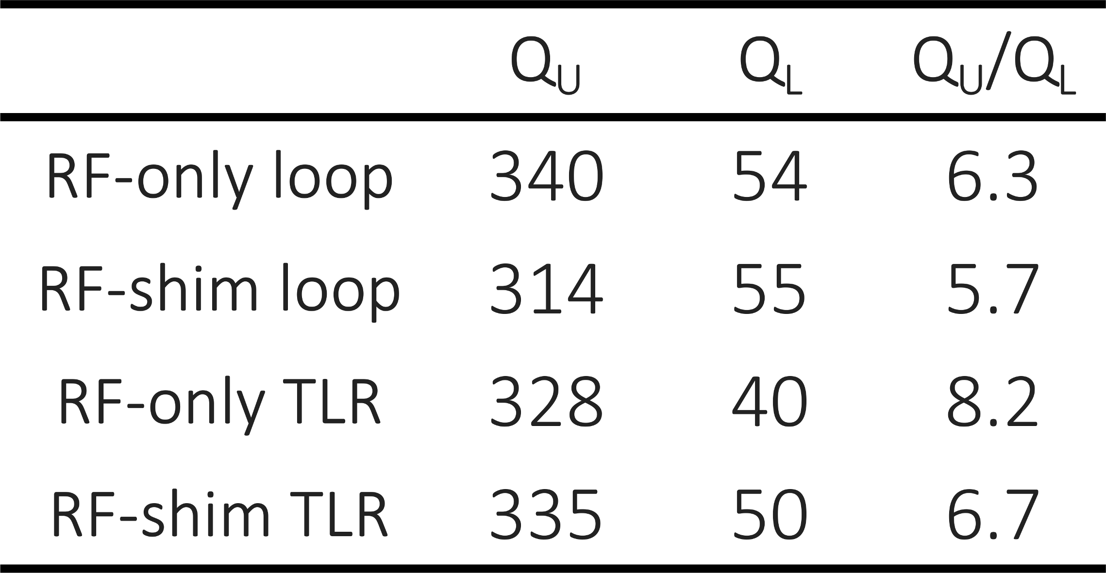
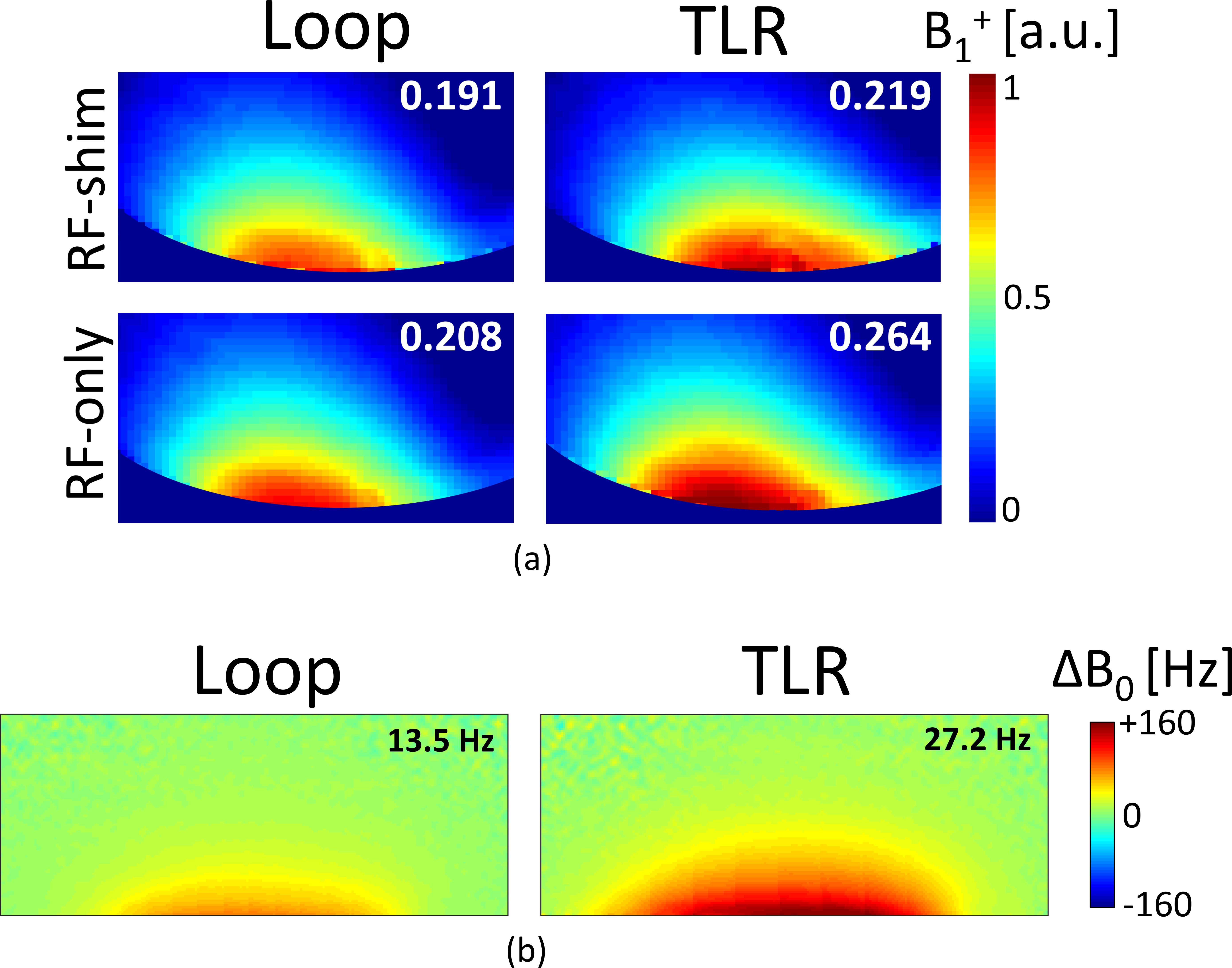
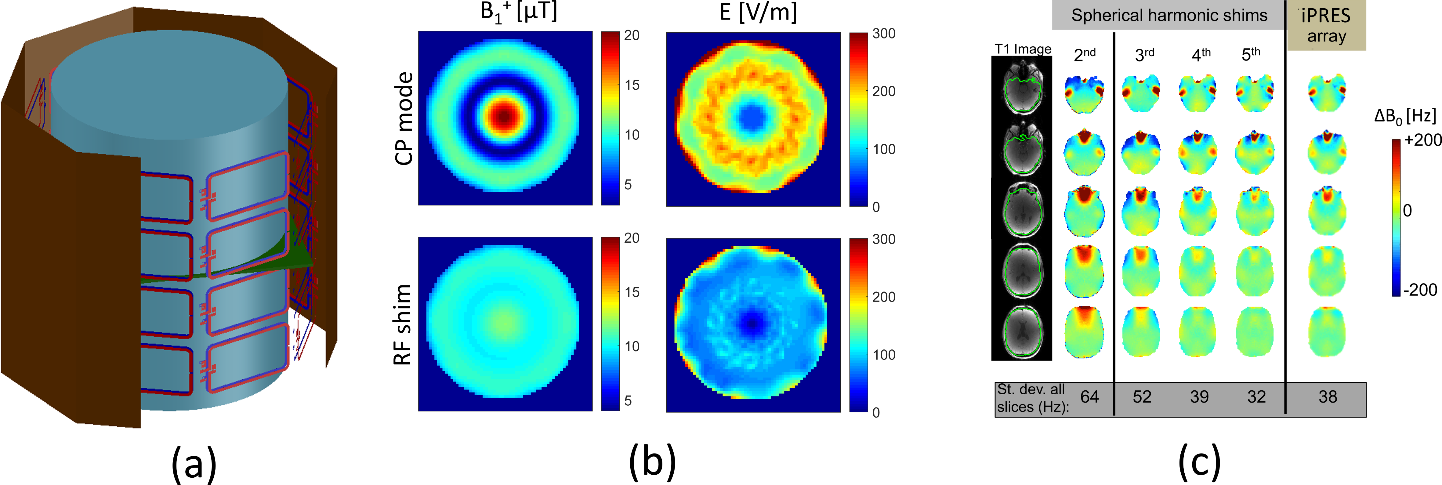
Table 1 shows the Q factors measured for the four comparison coils. The Q ratio (QU/QL) was higher for the TLR-based coil compared to the standard loop, both in RF-only and RF-shim versions. This indicates stronger coupling to the phantom for TLR-based coils. However, the larger drop in Q ratio upon addition of chokes indicates greater sensitivity of TLR-based coils to the presence of chokes. The B1 maps in Figure 3 confirm these trends. The B1 efficiency of the TLR is higher than that of the standard loop (on average over the slice, +13% and +21% compared to the RF-shim and RF-only versions, respectively). The insertion of chokes caused a drop in B1 efficiency, which was stronger for the TLR than the standard loop: -18% and -8%, respectively. The B0 maps show that, as expected, the TLR was 2x more efficient than the standard loop for generating B0 offsets. Figure 4 (center) shows that a 32-channel iPRES array will have similar B1 efficiency as standard quadrature volume coils, and that using SAR-aware RF shimming, high B1 homogeneity (<5%) can be achieved while maintaining similar efficiency (12μT for 1 kW input power) and lower SAR (54% average over the volume) compared to CP mode. Figure 4 (right) shows that the whole-brain B0-shim performance of the 32-channel iPRES array is similar to 4th order spherical harmonic shimming.Discussion and Conclusion
We have demonstrated that the TLR can be easily modified to act as a high performance coil element for combined Transmit, Receive and B0-shimming. In this work, we tested a particular geometry in which the standard loop and the TLR needed the same number of chokes; despite this, the TLR was shown to be significantly more efficient at generating both B1 and B0 fields. Several inter-element decoupling designs are available, including capacitive, transformer or shielding ring decoupling2,3. We therefore conclude that the TLR-shim design forms an excellent foundation for the first practical iPRES array.Acknowledgements
The authors acknowledge research support from the NIH (P41 EB015891, 1 S10 RR026351-01A1), GE Healthcare, and Zurich MedTech AG (Sim4Science program).References
[1] Serfaty, Stéphane, et al. "Multi-turn split-conductor transmission-line resonators." Magnetic Resonance in Medicine 38.4 (1997): 687-689.
[2] Kriegl, R., et al. "Multi-turn multi-gap transmission line resonators – concept, design and first implementation at 4.7 T and 7T." Journal of Magnetic Resonance 273 (2016): 65-72.
[3] Kriegl, R., et al. "Novel inductive decoupling technique for flexible transceiver arrays of monolithic transmission line resonators." Magnetic Resonance in Medicine 73.4 (2015): 1669-1681.
[4] Stockmann, Jason P., et al. "A 32-channel combined RF and B0 shim array for 3T brain imaging." Magnetic Resonance in Medicine 75.1 (2016): 441-451.
[5] Truong, T.K., et al. "Integrated RF/shim coil array for parallel reception and localized B0 shimming in the human brain." NeuroImage 103 (2014): 235-240.
Figures
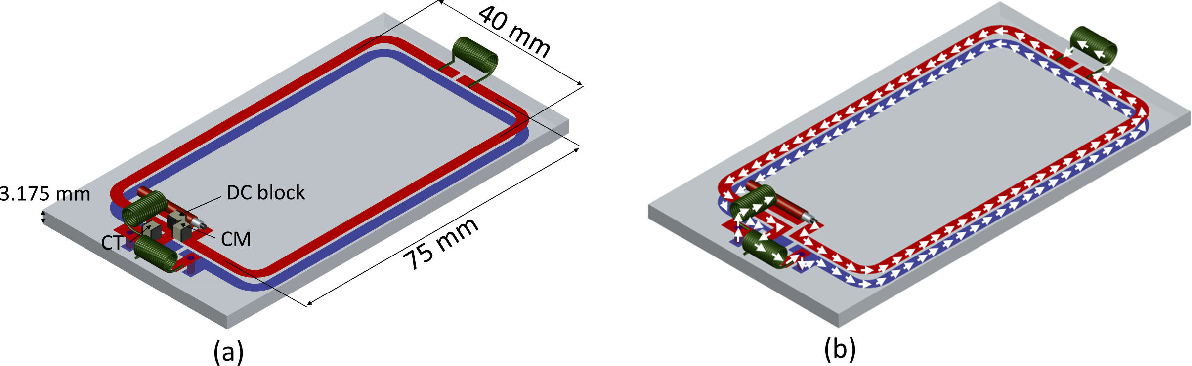
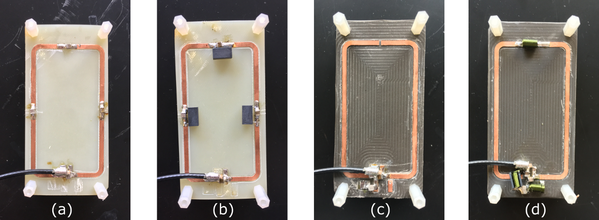
Figure 2: Top layer of the 4 prototypes: (a) simple loop, RF-only; (b) simple loop, RF-shim; (c) TLR coil, RF-only; (d) TLR coil, RF-shim. All prototypes were fabricated on a milling machine to assure tight dimensional tolerances and to better control the strip width on the TLR coils.