0963
Combined imaging and shimming with the Dynamic Multi-Coil Technique1Yale School of Medicine, New Haven, CT, United States, 2RWTH Aachen University, Aachen, Germany
Synopsis
Spatial encoding and shimming in MRI commonly use dedicated coils that generate spherical harmonic fields. Recently introduced dynamic multi-coil technique (DYNAMITE) demonstrates that MRI-relevant magnetic fields can also be created by a generic set of coils that produce non-linear and non-orthogonal fields, through successful implementation of dynamic shimming, linear and non-linear encoding. Here, purely DYNAMITE-based, concurrent spatial encoding and B$$$_{0}$$$ shimming is demonstrated. The successful synthesis of all encoding and shimming fields with DYNAMITE encourages the simplification of MR scanner architecture by substitution of multi-layer spherical harmonic coil systems with a single-layer multi-coil array.
Purpose
Spatial encoding and shimming in MRI have traditionally been performed using dedicated coils that generate spherical harmonic fields, e.g. linear X, Y and Z gradients for spatial encoding and linear and higher order fields for shimming. The recently introduced Multi-coil hardware has proven that MRI-relevant magnetic fields can also be created by a generic set of localized coils producing non-linear and non-orthogonal fields, through successful implementation of dynamic shimming [1–3], linear and non-linear encoding [4–6]. As a step towards establishing a purely Multi-coil-based MRI field generation system, the feasibility of concurrent spatial encoding and shimming is demonstrated in this study. We report the use of Dynamic Multi-Coil Technique (DYNAMITE) for combined Cartesian encoding and shimming.Methods
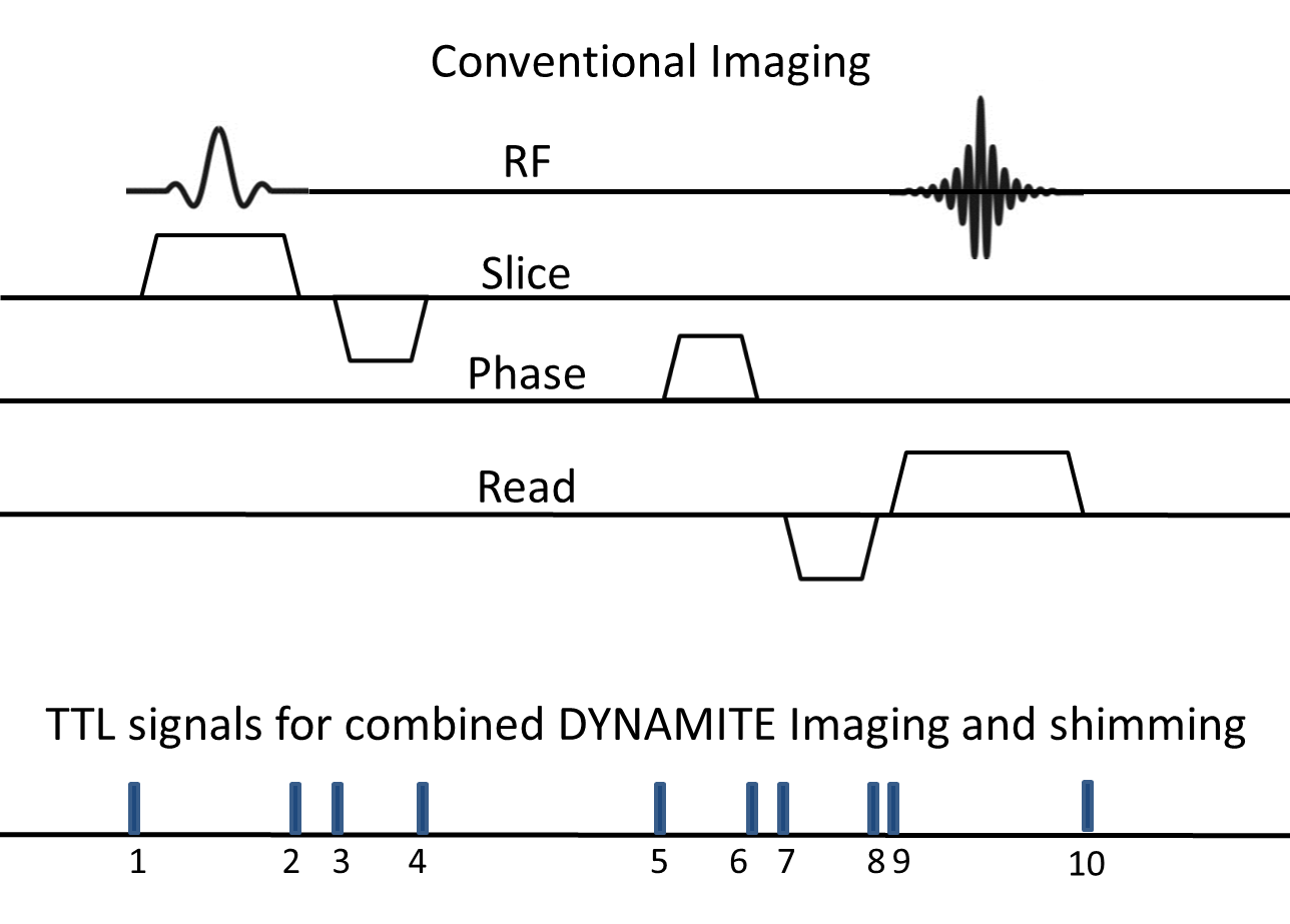
All experiments were performed on a 9.4 T pre-clinical scanner on a phantom object and a piece of carrot. The Multi-coil hardware used in this study has been described earlier [6] and comprises of 48 independently driven circular coils. A gradient echo (GE) MRI sequence with Cartesian Fourier-encoding was implemented with the ability to replace system-generated linear X, Y and Z gradient fields by the equivalent gradient fields generated purely by the Multi-coil hardware. DYNAMITE imaging was furthermore extended by concurrent DYNAMITE shimming with the same setup. All current settings for DYNAMITE imaging and shimming were estimated using least-squares optimization [6], based on calibration information obtained using asymmetric spin-echo B$$$_{0}$$$ mapping. The common acquisition parameters were- FOV: 12x12x11 mm$$$^{ 3}$$$ , 11 slices(1 mm thick), Resolution: 128x128, TE: 10 ms, TR: 0.5 s, maximum gradient strength (readout, phase encode and slice) 25 kHz/cm, Bandwidth: 30 kHz.
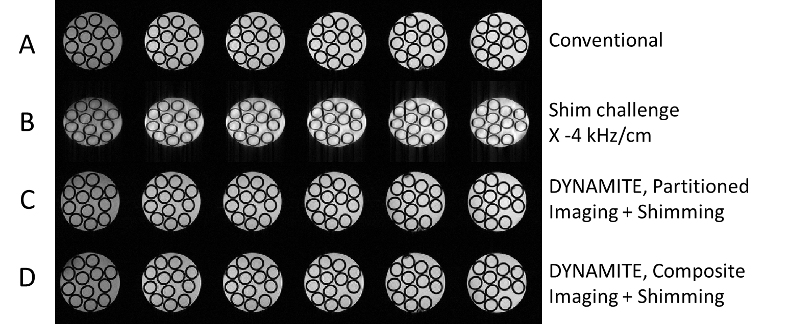
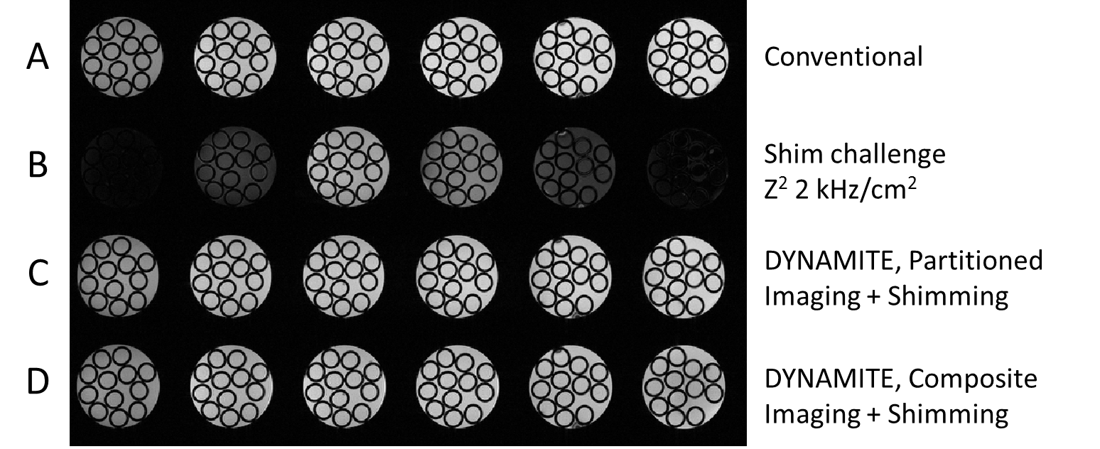
To test the combined DYNAMITE imaging and shimming capability, the system spherical harmonic coils were used to create different shim challenges, namely -4 kHz/cm in X direction and 2 kHz/cm$$$^{2}$$$ Z$$$^{2}$$$ . Two different approaches for combined DYNAMITE imaging and shimming were compared. In the first approach, currents needed for generating imaging and shimming fields were partitioned at predefined current-range of 85% of the total dynamic range of ± 1 A for imaging verses 15% for shimming, and calculated separately. The sum of both 48-current vectors was then used during acquisition. In the second approach, the target imaging and shim fields were combined first and coil currents that achieved the best composite fit were calculated directly. The baseline condition (no gradient events) for both DYNAMITE imaging and shimming implementations used 100% currents for shimming.
Results
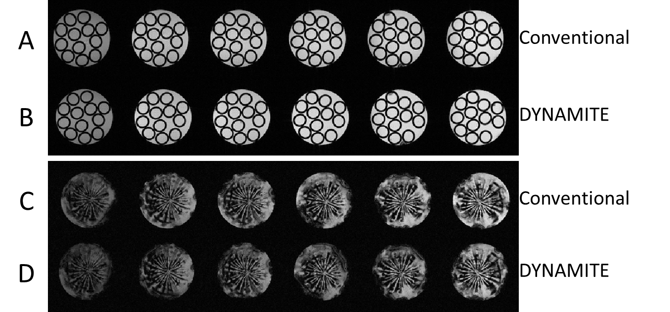
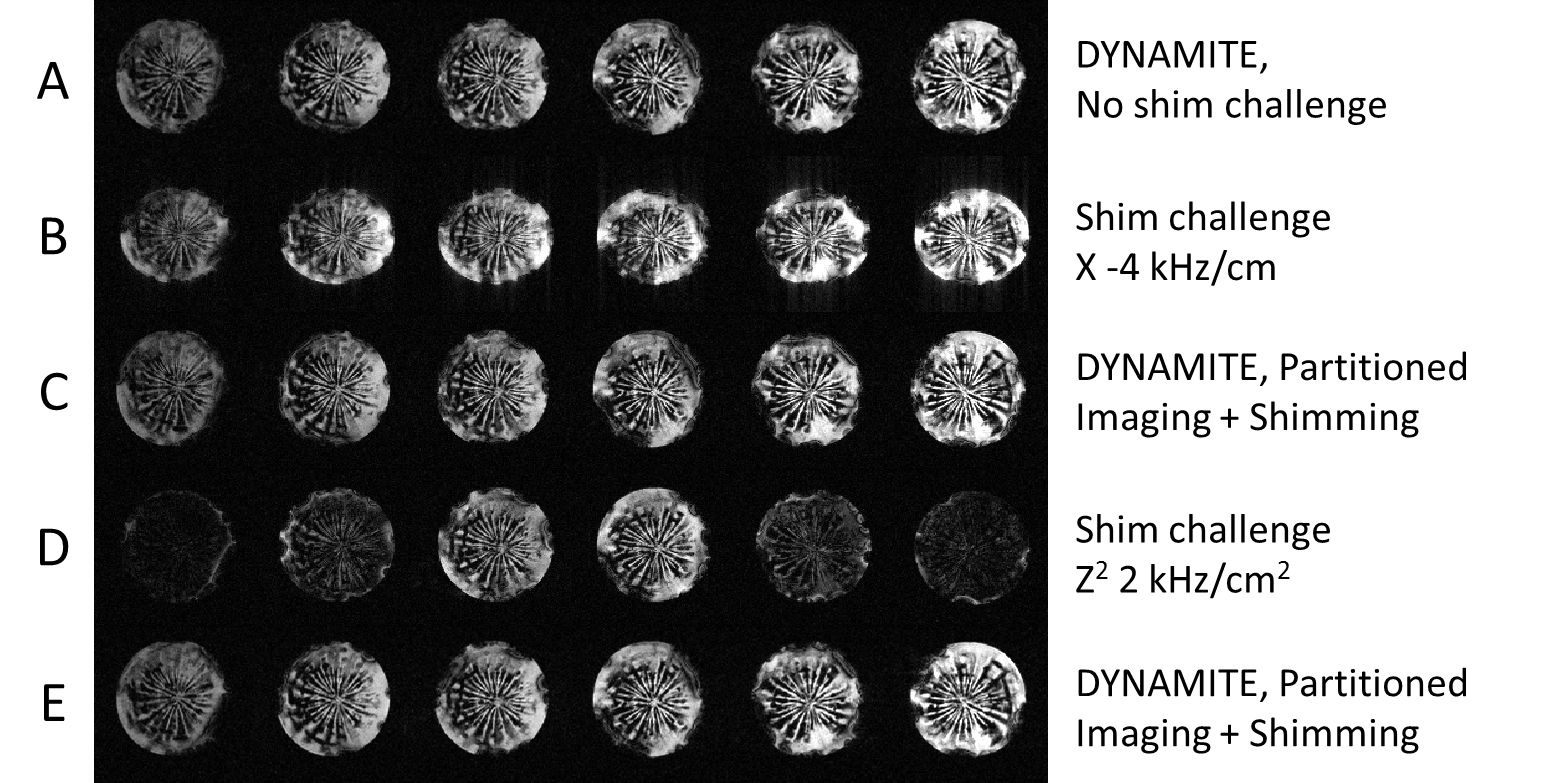
Images obtained with DYNAMITE imaging with 85% current capacity were virtually identical to those acquired with the conventional set of the scanner‘s built-in gradient coils (see Fig. 2), indicating that the remaining 15% current could be used for shimming. A shim challenge in X-direction (opposed to read gradient field), would have resulted in severe image distortion (see Fig. 3). Combined DYNAMITE imaging and shimming corrected this image distortion completely as shown in Fig. 3. The Z$$$^{2}$$$-shaped B$$$_{0}$$$ distortion resulted in severe signal loss especially in the FOV periphery (see Fig. 4). Combined DYNAMITE imaging and shimming restored the signal loss completely. The performance of partitioned and composite DYNAMITE imaging and shimming were nearly identical. Similar results were obtained in a carrot (Fig. 5). Notably, similar MRI experiments employing a spin-echo instead of a gradient-echo MRI sequence yielded equivalent results (data not shown).Discussion
Here we demonstrate the first successful implementation of combined DYNAMITE imaging and shimming. Our results endorse the potential of Multi-coil hardware as a full-fledged imaging and shimming system. DYNAMITE has previously been shown to possess excellent capabilities for dedicated encoding or shimming applications [1, 3, 6]. Our results show that both these benefits can be concurrently availed using the same set of coils.Acknowledgements
No acknowledgement found.References
1. Juchem C, Brown PB, Nixon TW, McIntyre S, Rothman DL, and de Graaf RA. Multicoil shimming of the mouse brain. Magnetic Resonance in Medicine, 2011, 66(3):893–900.
2. Juchem C, Nixon TW, McIntyre S, Boer VO, Rothman DL, and de Graaf RA. Dynamic multi-coil shimming of the human brain at 7T. J Magn Reson, 2011, 212:280 – 288.
3. Juchem C, Rudrapatna SU, Nixon TW, and de Graaf RA. Dynamic multi-coil technique (DYNAMITE) shimming for echo-planar imaging of the human brain at 7 Tesla. NeuroImage, 2015, 105:462– 472.
4. Juchem C, Nixon TW, McIntyre S, Rothman DL, and de Graaf RA. Magnetic field modeling with a set of individual localized coils. Journal of Magnetic Resonance, 2010, 204(2):281 – 289.
5. Juchem C, Nixon TW, and de Graaf RA. Multi-coil imaging with algebraic reconstruction. ISMRM,2012, (2545).
6. Juchem C, Nahhass OM, Nixon TW, and de Graaf RA. Multi-slice MRI with the dynamic multi-coil technique. NMR in Biomedicine, 2015, 28(11):1526–1534.
Figures