0920
Anthropomorphic Spinal Cord Phantom with Induced Field Inhomogeneity1Translational and Molecular Imaging Institute, Icahn School of Medicine at Mount Sinai, New York, NY, United States, 2Department of Radiology, Icahn School of Medicine at Mount Sinai, New York, NY, United States, 3Graduate School of Biomedical Sciences, Icahn School of Medicine at Mount Sinai, New York, NY, United States, 4Department of Mechanical Engineering, The City College of New York, New York, NY, United States, 5Department of Neuroscience, Icahn School of Medicine at Mount Sinai, New York, NY, United States
Synopsis
The human spinal cord exists in a particularly unfavorable magnetic field environment. Technical development of diffusion and functional MRI methods would be facilitated by a phantom to model spatially and temporally periodic field inhomogeneities. We have designed a phantom capable of simulating these specific field disturbances. The spinal canal was machined from acrylic, and the cord was cast of polyvinyl alcohol. The phantom was imaged using anatomical CT and MRI, and functional and diffusion EPI protocols. The phantom has relaxation and diffusion properties similar to the human cord, and air-filled vials create spatially periodic frequency shifts of -100 Hz.
Introduction
The human spinal cord contains important neural tracts and circuits that can be assessed by MRI1, but exists in a particularly unfavorable magnetic field environment. The adjacent vertebral bodies and intervertebral discs, having different magnetic susceptibilities, create spatially periodic field distortions in the spinal canal. The lungs, which fill and empty of paramagnetic air, also create temporally-varying field disturbances2. The echo-planar imaging (EPI) sequences most commonly used in functional and diffusion studies are especially sensitive to field disturbances3. Development of advanced shimming techniques, pulse sequences, and reconstruction techniques robust to these field disturbances has been actively pursued by the spinal cord MRI research community. To facilitate these technical developments, we have designed and constructed a phantom of the human spinal cord and canal capable of simulating these specific field disturbances.Methods
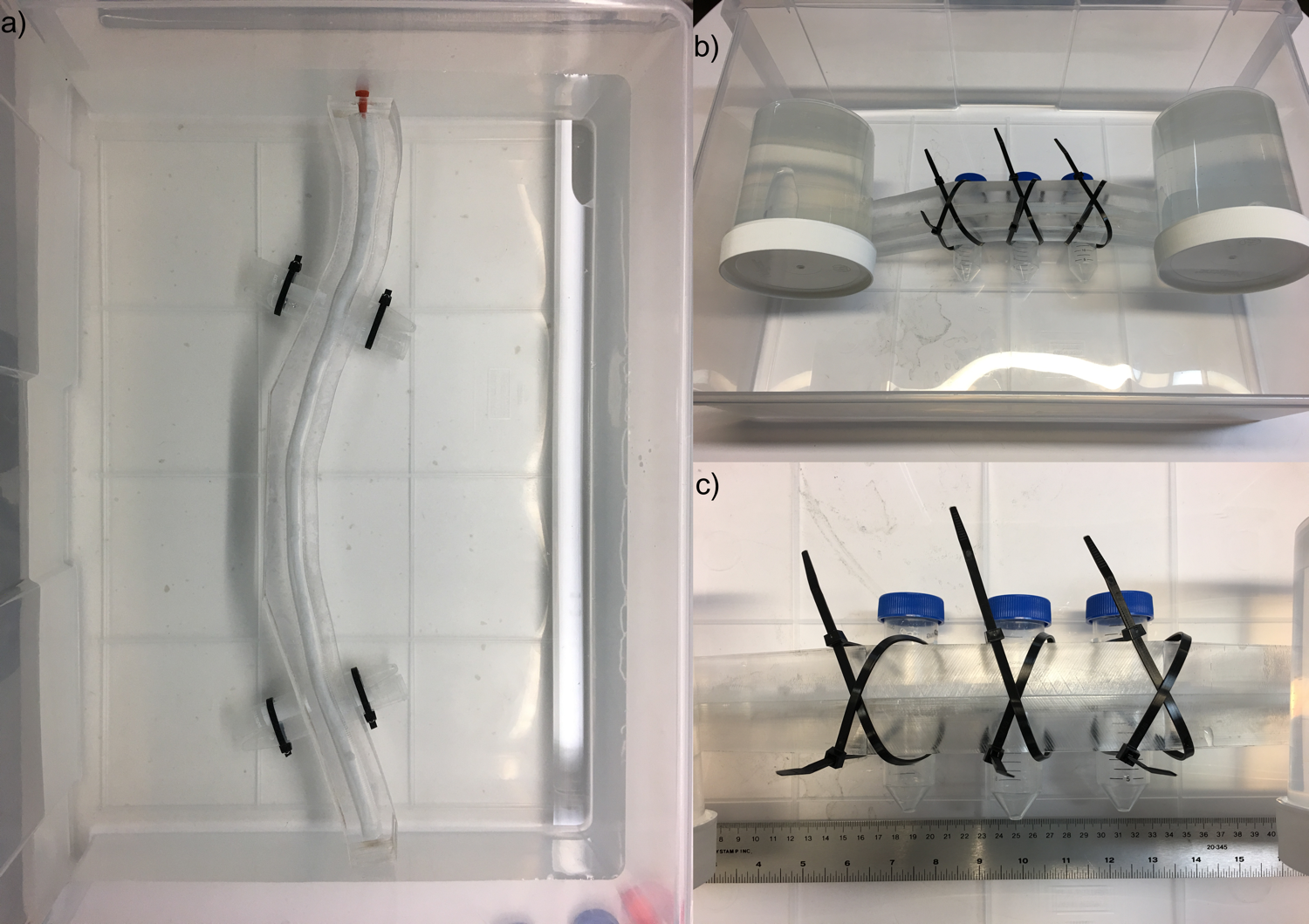
Phantom: The spinal cord and canal between the C1 and L1 vertebral levels were modelled in SolidWorks CAD software (Dassault Systèmes, Waltham, MA) based on in vivo measurements4,5,6. The two halves of the canal were machined on two optically clear acrylic sheets, and the sheets were trimmed of excess material outside the canal. A solution of 16% w/w polyvinyl alcohol (PVA)7,8,9 in distilled water was injected into a 3D printed mold of the spinal cord and allowed to solidify before removal from the mold. The denticular ligaments, 8 in the cervical cord and 4 in the thoracic cord, were attached to the walls of the acrylic canal with silicone epoxy adhesive, and the two halves of the acrylic canal were sealed together using acrylic adhesive (Weld-On 4, SciGrip, Durham, NC). The phantom was filled with distilled water through a filler hole drilled in one end, and sealed with a silicone rubber stopper.
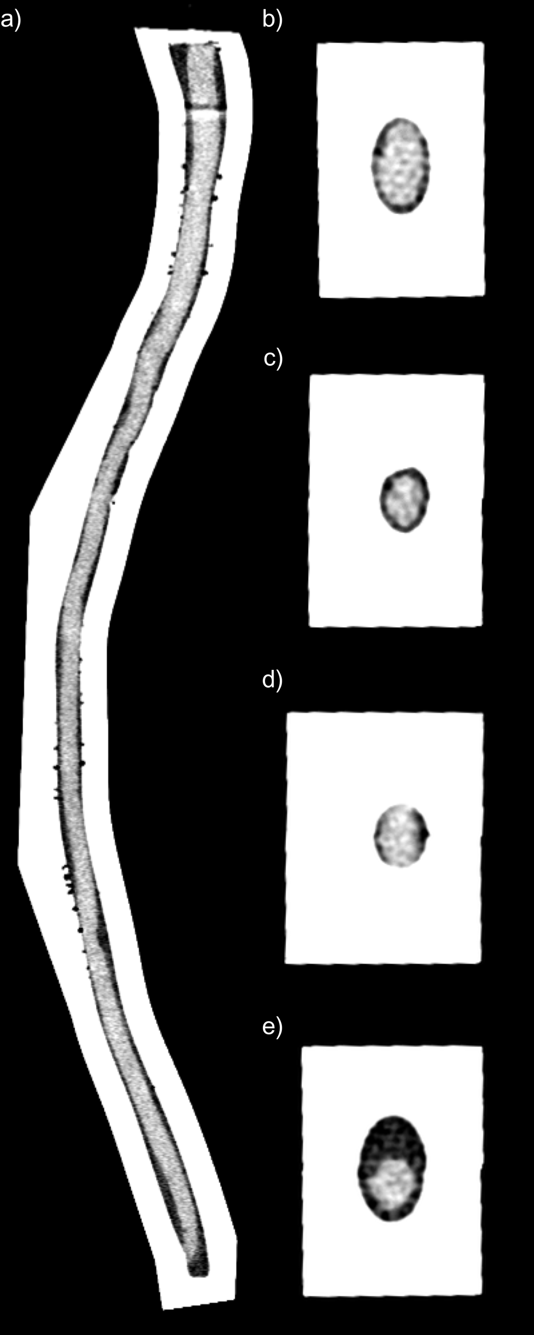
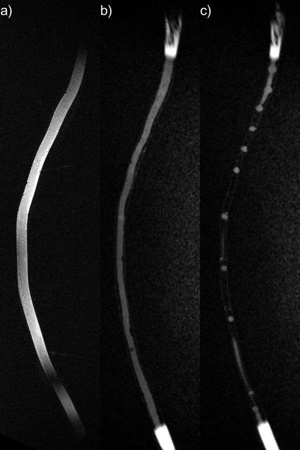
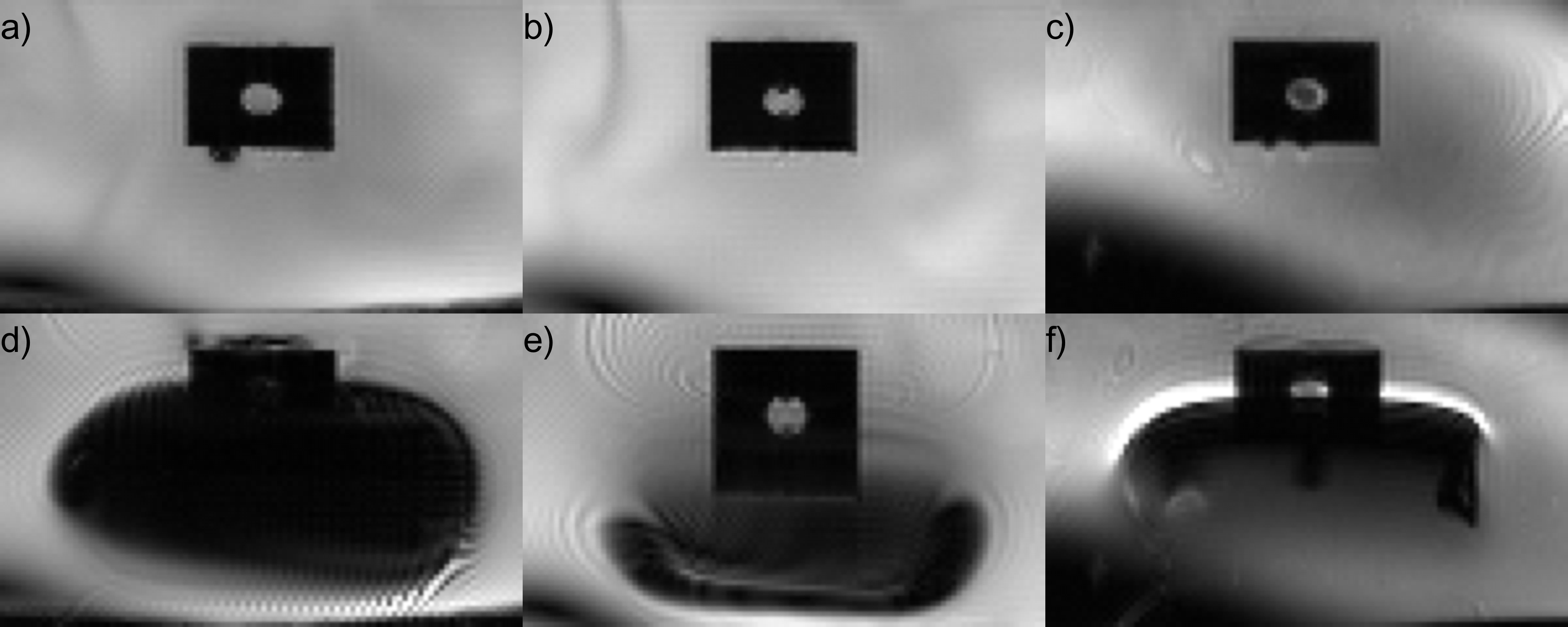
CT and MRI: The phantom was imaged using Force CT and Skyra 3T MRI scanners (Siemens, Erlangen, Germany). Axial CT images were reconstructed at 250x250x500 µm3 resolution. Anatomical MR images were acquired using 3D sagittal T2-weighted turbo-spin echo (SPACE, 0.5 mm isotropic, TR/TE = 3200/569 ms, GRAPPA R=2) and T1-weighted inversion-recovery GRE (MP-RAGE, 1.0 mm isotropic, TR/TE/TI = 3000/1.31/1000 ms, flip angle = 8°) sequences. Echo-planar imaging and field mapping were performed with the phantom immersed in a tub of water with and without three 50-mL vials of air tethered to the phantom to create susceptibility-induced field distortions. Illustrative EPI data were acquired using BOLD fMRI (GRE-EPI, 1.75x1.75x5.0 mm3, 12 slices, 5-mm gap, TR/TE = 1200/50 ms, flip angle = 77°, phase encoding AP, BW = 1502 Hz/px, ETL = 72, echo spacing = 0.75 ms) and diffusion MRI (SE-EPI, 1.75x1.75x5.0 mm3, 1 slice, TR/TE = 2000/200 ms, flip angle = 90°, 4 averages, b = 0, 400 s/mm2, otherwise identical to above). Field maps were computed from dual-echo GRE scans (1.5 mm isotropic, TR/TE1/TE2 = 1200/4.7/9.4 ms).
Results
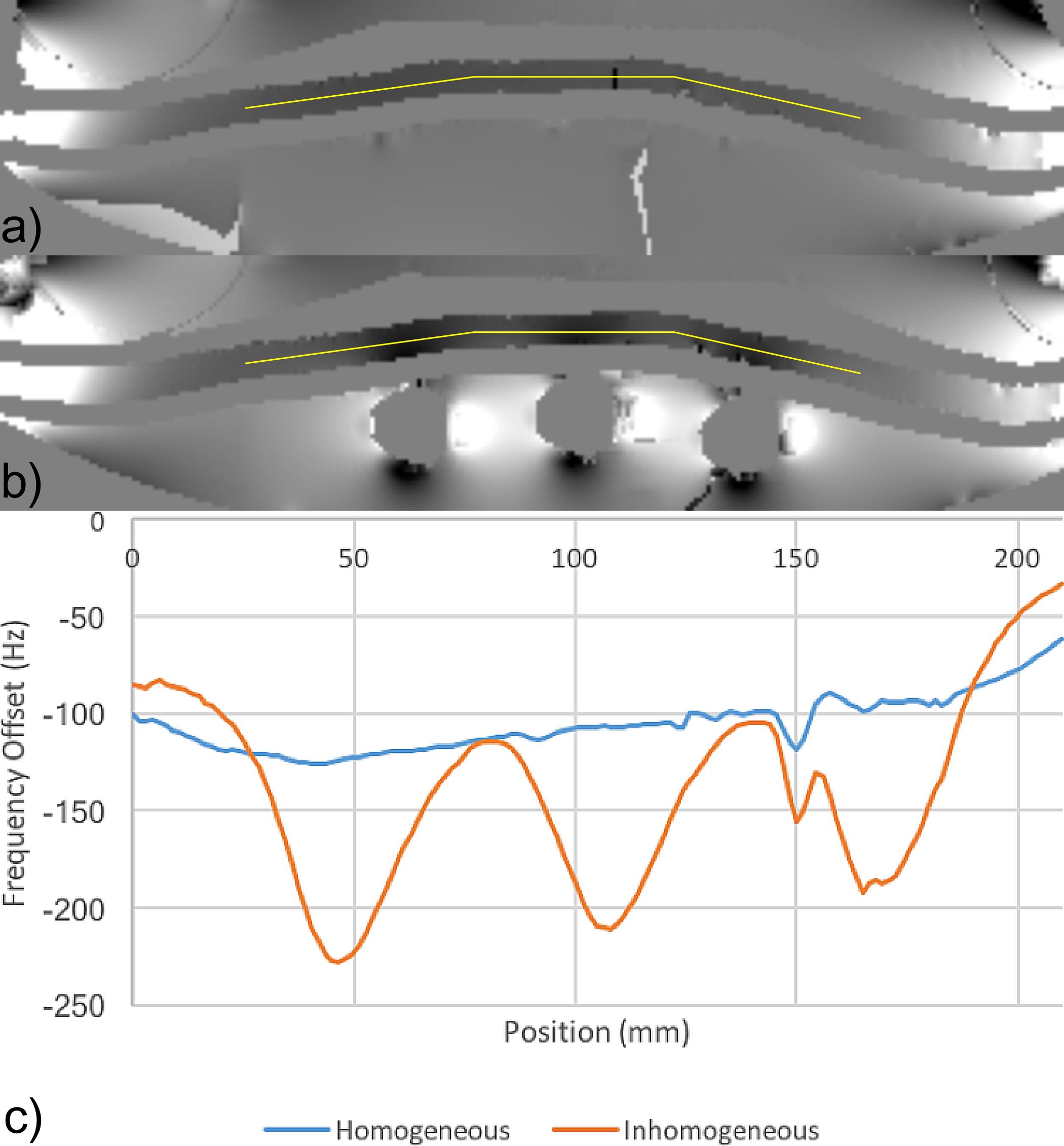
The phantom is shown in photographs (Figure 1), CT images (Figure 2), and T1- and T2-weighted MR images (Figure 3). In Figure 4, distortion and signal drop-out caused by magnetic field inhomogeneities (Figure 1b,c) are demonstrated. Air-filled vials create spatially-periodic frequency shifts of -100 Hz within the spinal canal (Figure 5). T1 of the PVA spinal cord was 839 ms, T2 was 107 ms, and the apparent diffusion coefficient (ADC) was 1.480 µm2/ms.Discussion
This phantom was designed to accurately reproduce normal adult human anatomy and mimic MR properties in healthy human spinal cord10,11. Both T1 and T2 relaxation times and ADC are determined by the concentration of PVA, and are all within reasonable ranges in our current phantom prototype. Our design did not allow distinction of gray and white matter due to the anatomical complexity; neither did we attempt to fully reproduce every dentate ligament in the human spinal cord or other small structures in the spinal canal. Similar consideration (i.e., trade-off between design complexity and realistic anatomical and physiological representation) has led us to exclude mimicking pulsation of cerebrospinal fluid (CSF) in our initial phantom design.
The phantom was constructed with minimal excess material outside the spinal canal, making it possible to place materials which create field inhomogeneities as near as possible to the spinal cord. Optimal choice and placement of the materials will be explored to create spatially periodic field inhomogeneities. In addition, future phantom development will make use of inhomogeneities that are periodic in both space and time to simultaneously simulate the effects of vertebrae and respiratory motion on the magnetic field in the spinal canal.
Conclusion
This phantom will facilitate and accelerate technical improvements to imaging methods in the spinal cord.Acknowledgements
No acknowledgement found.References
[1] Stroman PW, Wheeler-Kingshott C, Bacon M, et al. The current state-of-the-art of spinal cord imaging: methods. Neuroimage 2014;84:1070-1081.
[2] Verma T, Cohen-Adad J. Effect of respiration on the B0 field in the human spinal cord at 3T. Magn Res Med 2014;72(6):1629-1636.
[3] Jezzard P, Balaban RS. Correction for geometric distortion in echo planar images from B0 field variations. Magn Res Med 1995;34(1):65-73.
[4] Sherman JL, Nassaux PY, Citrin CM. Measurements of the Normal Cervical Spinal Cord on MR imaging. Am J Neuroradiology 1990;11:369–72.
[5] Gellad F, Rao KC, Joseph PM, et al. Morphology and dimensions of the thoracic cord by computer-assisted metrizamide myelography. Am J Neuroradiology 1983;4:614-617.
[6] Zaaroor M, Kosa G, Peri-Eran A, et al. Morphological Study of the Spinal Canal Content for Subarachnoid Endoscopy. Minim Invasive Neurosurg 2006;49(4):220-226.
[7] Surry KJ, Austin HJ, Fenster A, et al. Poly (vinyl alcohol) cryogel phantoms for use in ultrasound and MR imaging. Phys Med Biol 2004;49(24):5529-5546.
[8] Chu KC, Rutt BK. Polyvinyl alcohol cryogel: an ideal phantom material for MR studies of arterial flow and elasticity. Magn Res Med 1997;37(2):314-319.
[9] Reinertsen I, Collins DL. A realistic phantom for brain-shift simulations. Medical Physics 2006;33(9):3234-3240.
[10] Smith SA, Edden RA, Farrell JA, et al. Measurement of T1 and T2 in the cervical spinal cord at 3 Tesla. Magn Reson Med. 2008;60(1):213–219.
[11] Xu J1, Shimony JS, Klawiter EC, et al. Improved in vivo diffusion tensor imaging of human cervical spinal cord. Neuroimage 2013;67:64-76.
Figures