0784
Implementation of a 2.4 GHz wireless sensing platform for transmission of motion data from within a head coil at 3T.1Division of Biomedical Engineering, Human Biology, University of Cape Town, Cape Town, South Africa, 2Athinoula A. Martinos Center, Massachusetts General Hospital, Charlestown, MA, United States, 3Radiology, Harvard Medical School, Boston, MA, United States
Synopsis
Prospective motion correction using external hardware can be compromised by poor marker attachment. In this work we introduce a new attachment site on the mastoid process of the subject. To achieve this, an active wireless marker is implemented that takes advantage of the versatility of an existing method (VectOrient). The effects of the device on the scanner’s operation and visa versa are evaluated. The small 14x16mm2 device shows good MRI compatibility. Any degradation in signal quality is localised and could be further reduced. The link quality is sufficient to stream patient motion parameters, quantifying patient pulse during MEMPRAGE and EPI pulse sequences.
Purpose
A challenge in marker-based prospective motion correction lies in the trade-off between subject-comfort and how well the marker is attached to the subject’s skull1. In this work we design and fabricate a device that can be used for real-time monitoring of patient orientation through the previously proposed VectOrient2 method. VectOrient allows unlimited measurement range, no line-of-sight requirement and estimates orientation from a single point. VectOrient does, however, require a low latency active data link from within the receive coil. To address marker fixation and MRI compatible data transfer, we propose implementing a 2.4 GHz radio small enough to fit on the mastoid process. Here the skin is much less likely to move relative to the skull and any susceptibility artefacts are localised to the auditory canal.Methods
The printed-circuit-board (PCB) was laid out to minimise loop area, eliminate copper where possible, and reduce overall size (~14 x 16 mm2). Figure 1A shows the 4-layer PCB layout; a tree-like configuration was used for signal routing. The device comprises a 3-axis accelerometer, 3-axis angular rate sensor, 3-axis magnetometer, microcontroller and 2.4 GHz radio (CC2500, Texas Instruments, Dallas, USA). The microcontroller and radio are both clocked at 26 MHz from a micro-electromechanical oscillator (SiT8008, SiTime, California, USA) with programmable drive strength, for a reduction in harmonics. The absence of a ground plane on the small ceramic monopole antenna implemented initially (Fig. 1A) resulted in poor performance. Link integrity was improved by implementing a wire dipole antenna on the same footprint (Fig. 1B). An inductor-capacitor resonant circuit tuned to the Larmor frequency was placed across the radio output pins to reduce harmonic emissions, filter the 2.4 GHz signal and protect the output stage. Firmware was developed to ensure accurate control of the radio state. The radio was set up for a 50 kbps data rate using minimum-shift-keying (MSK) modulation. The effect of the device’s operation on scanner performance was assessed using standard quality assurance sequences (3T Skyra, Siemens, Erlangen, Germany). Link quality was evaluated by measuring the packet error rate during Multi-echo MPRAGE3 and 2D-EPI acquisitions. In vivo scans with and without the device were compared for MEMPRAGE and 2D-EPI sequences to evaluate changes in image quality and the robustness of the marker fixation point.Results
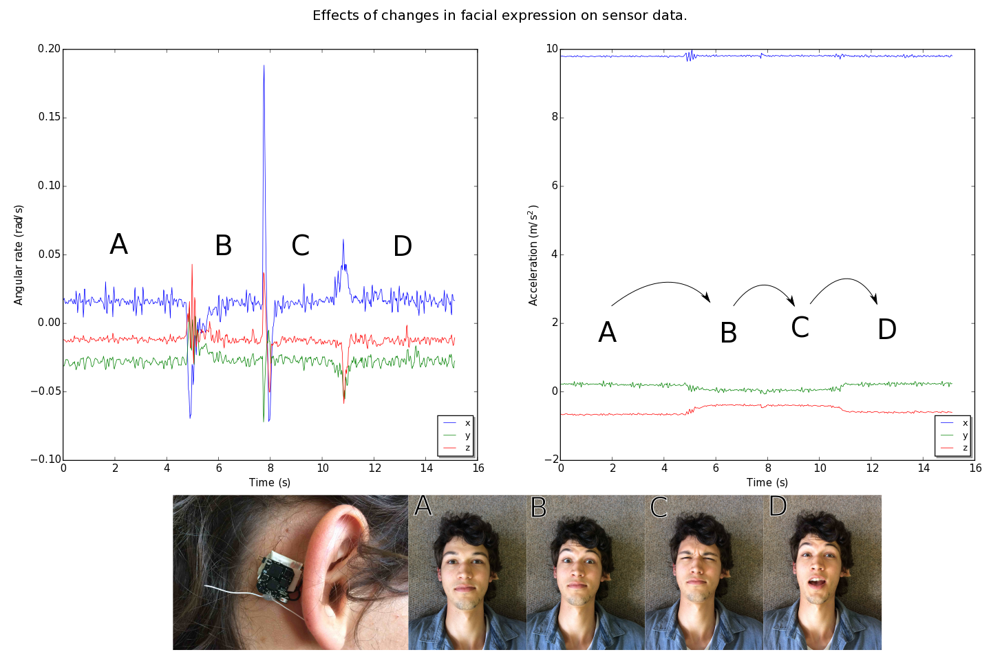
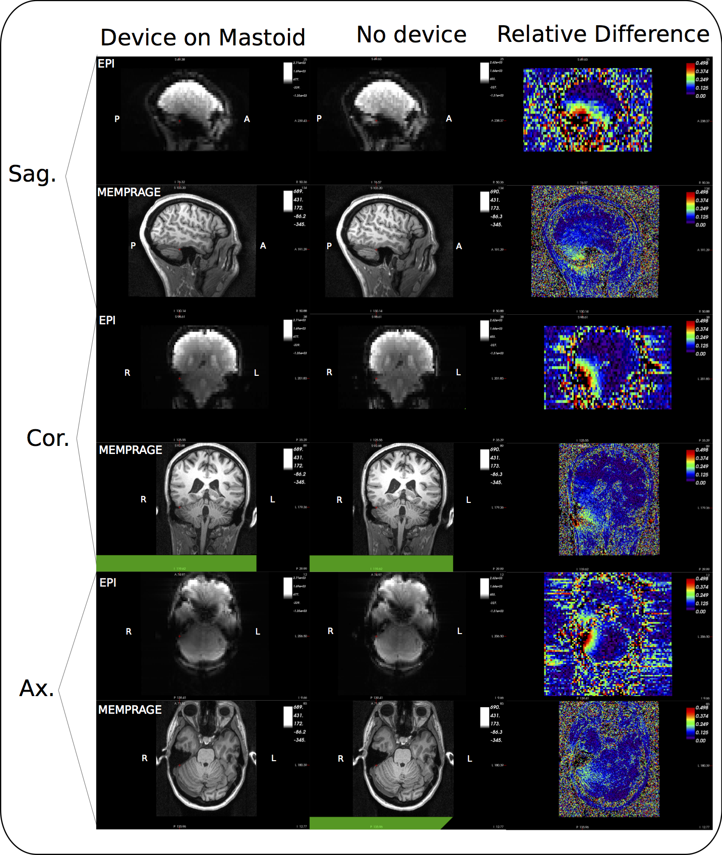
RF noise and spike tests were passed with only a small ripple in the RF spectrum at 250 kHz from the centre frequency. During the 32ch head coil test, only channels in close proximity to the device showed SNR deficits (Fig. 2). Moving the device from the forehead to mastoid region on the phantom showed a reduced effect on overall SNR. Although a packet rate of 200 Hz was possible, bit errors caused by RF pulses made data transfer unreliable during scanning. Enabling forward error correction (reducing the packet rate to 50 Hz) allowed more robust transfers. Interestingly, during phantom scans, EPI affected link performance minimally (Fig. 3A). Differences in data acquired during ex vivo and in vivo scans highlight the effect of involuntary subject motion (Fig. 3B). The subject’s pulse is visible during the MEMPRAGE sequence and scanner bed vibrations are amplified during EPI. Mounting the device on the mastoid process showed little deviation with changes in facial expression (Fig. 4). In vivo images showed relative signal loss around the region of device fixation with the effect being more pronounced during EPI (Fig. 5).Discussion
Mounting the wireless device on the mastoid process reduces its effect on SNR, presumably because the 32ch coil is optimised for neuroimaging, and improves fixation robustness and subject comfort. Although a reliable link was achieved, the repetitive nature of gradient and RF activity suggests that link strength could be monitored and the radio synchronised with the pulse sequence. Increasing data rate for burst transmissions would reduce interference allowing one to take full advantage of the high bandwidth sensors. The precise measurements of angular velocity and acceleration show that in gradient intensive pulse sequences like EPI involuntary motion is dominated by directional scanner vibration providing insight into better patient positioning.Conclusion
Clinical MRI can benefit from an easy to use single point of contact wireless device capable of quantifying subject orientation for prospective motion correction or measuring physiological signals for pulse sequence gating or more robust analysis of functional MRI data.Acknowledgements
I would like to thank Andrew Wilkinson and Marcin Jankiewicz for their help in RF design challenges and data acquisition respectively.
National Institutes of Health under grants R01HD071664, R21MH096559, the NRF/DST through the South African Research Chairs Initiative and the University of Cape Town through the RCIPS Explorer fund EX15-009
References
[1] Julian Maclaren, Michael Herbst, Oliver Speck, and Maxim Zaitsev. Prospective motion correction in brain imaging: a review. Magnetic resonance in medicine: of?cial journal of the Society of Magnetic Resonance in Medicine / Society of Magnetic Resonance in Medicine, 69(3): 621–36, March 2013. ISSN 1522-2594. doi: 10.1002/mrm.24314. URL http://www.ncbi.nlm. nih.gov/pubmed/22570274.
[2] Adam M.J. van Niekerk, Paul Wighton, Ali Alhamud, Matthew D. Tisdall, Andre J.W. van der Kouwe, and Ernesta M. Meintjes, High frequency orientation estimates for fast real-time motion correction using vector observations of gravity and the static magnetic field (B0), 24th Annual Meeting ISMRM(2016).URL: http://cds.ismrm.org/protected/16MPresentations/abstracts/0338.html
[3] A. J. W. van der Kouwe, T. Benner, D. H. Salat, B. Fischl, Brain morphometry with multiecho MPRAGE, NeuroImage, 40, 559–569 (2008).
Figures
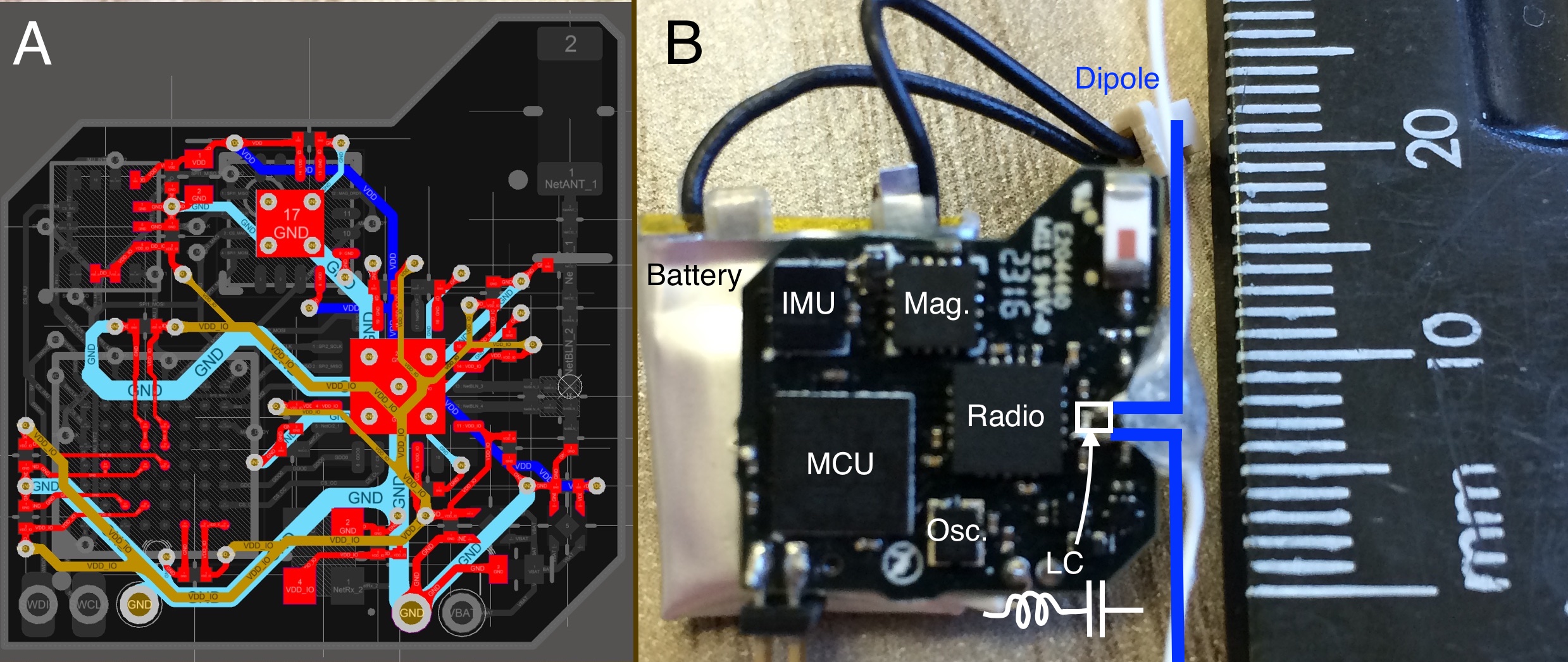
Figure 1:
A) The four layer PCB, layers from top to bottom (red, brown, turquoise and blue). Power supply and ground return paths are routed in an attempt to minimise loop area in the highlighted traces shown. 0603 (metric) passive components in standard packages were used in the PCB fabrication.
B) The finished device with modified wire dipole antenna to the right of the device.
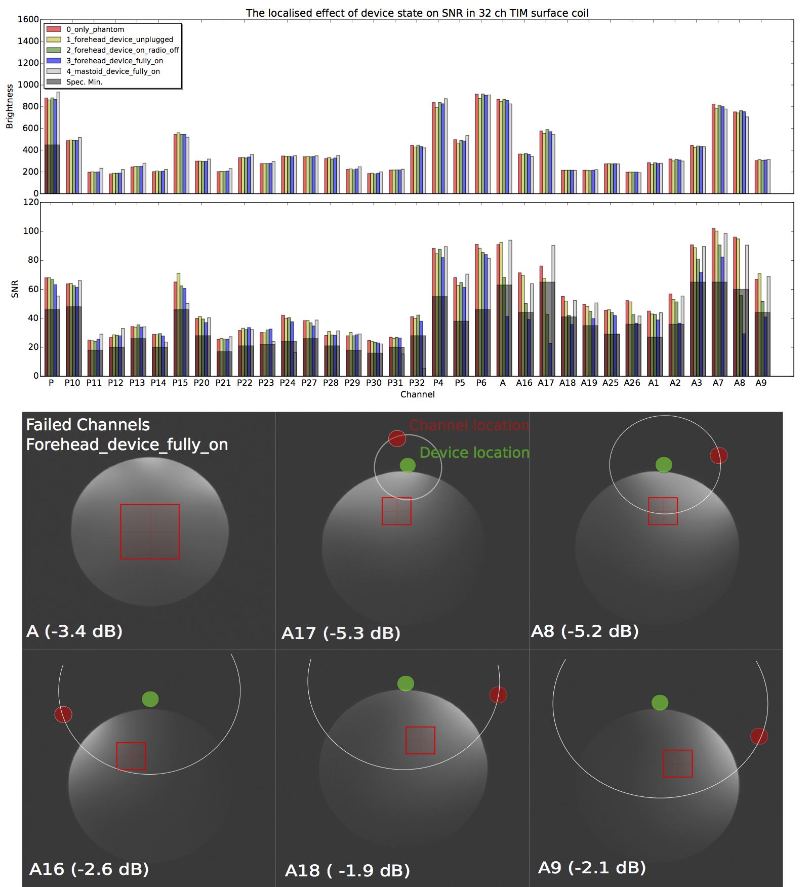
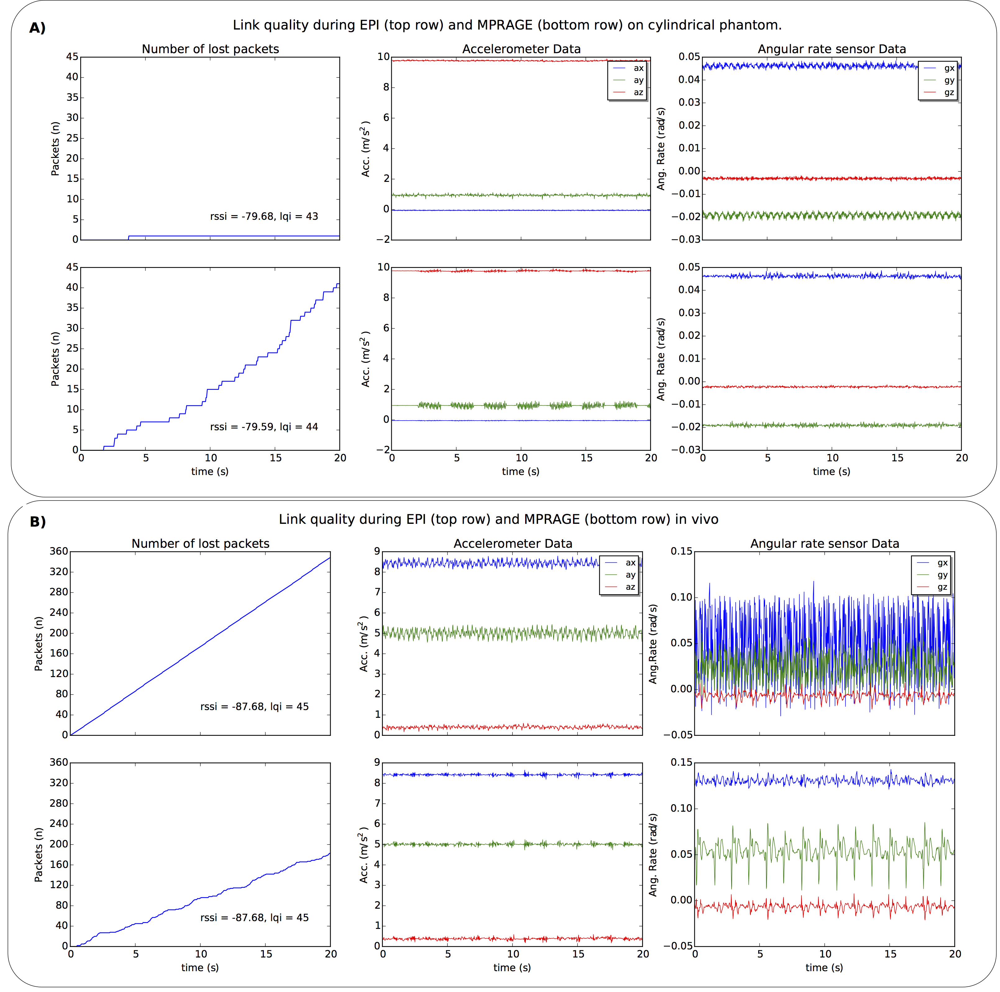
Figure 3: Data transmitted at 50 packets/s during scanning. The transmitter and receiver positions were the same for 2D-EPI and MEMPRAGE acquisitions.
A) Rolling motion of the cylindrical phantom about its long axis (y) is noticeable. Packet error rates correspond to 0.01% and 4.25% for the EPI and MEMPRAGE sequences, respectively.
B) In vivo data acquired with the sensor mounted on the mastoid process. The subject’s body caused a ~8dBm drop in signal and higher packet error rate, resulting in aliasing in the EPI data. The (healthy) subject’s pulse of 46 bpm corresponds closely with the peaks present in the gz data.