0767
Top-Hat Dipole RF Coil with Large Field of View for 7 T Brain MR Imaging1Department of Electronics and Information Technology, Korea University, Seoul, Korea, Republic of, 2Research Institute for Advanced Industrial Technology, Korea University, Sejong City, Korea, Republic of, 3Department of Biomicrosystem Technology, Korea University, Seoul, Korea, Republic of, 4ICT Convergence Technology for Health & Safety, Korea University, Sejong City, Korea, Republic of, 5Korea Basic Science Institute, Cheongju, Chungcheongbuk-do, Korea, Republic of, 6BIU Clinical Science MR, Philips Korea, Seoul, Korea, Republic of, 7Department for Biometrics und Medical Informatics, Otto-von-Guericke University, Magdeburg, Germany, 8Advanced Institutes of Convergence Technology, Seoul National University, Seoul, Korea, Republic of
Synopsis
In ultra-high-field brain MR imaging, the coverage for imaging with the optimized protocol is constrained not only by scan time, but also by the coil structure. Since presently available surface loop RF coils have limited field of view, it is very difficult to achieve the coverage from the top of the head to the end of the cervical vertebrae. Prior solution to this problem was to increase the number of elements. However, it increases the complexity of coil array design thus causing difficulties in construction of the coils. In this paper, an 8-channel top-hat dipole receive RF coil is proposed for the brain imaging at 7 Tesla MRI. By enabling the coil tuning with novel tuning methods for shorter RF coil lengths but still with reasonable uniformity and SNR for more imaging field of view compared with multi-element loop coils.
INTRODUCTION
A radiative antenna, such as monopole antenna has been proposed to address more uniform B1 patterns than conventional RF coil at Ultra High Field (UHF) [1]. However, when applied in brain imaging, limited signal coverage is observed in monopole antenna due to the degradation in transmit and receive performance in the inferior region of the brain. One approach to overcome this problem is to insert the top-hats at the ends of the dipole antenna [2]. In this paper, a top-hat dipole receive RF coil is proposed with a two-channel transmission RF coil (Nova Medical Products, USA) and its performance reported. The Field-Of-View (FOV) coverage is evaluated and Signal-To-Noise Ratio (SNR) as well as noise correlations of the coil channels are measured, and the imaging results are compared with a 32-loop-element brain RF coil (Nova Medical Products, USA).METHODS
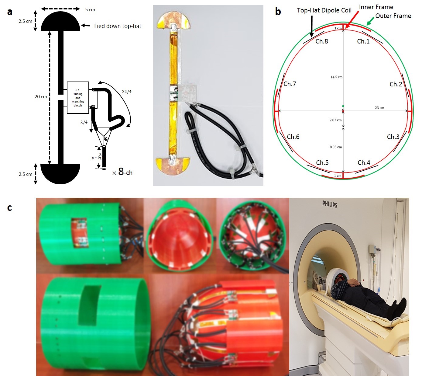
A top-hat receive dipole antenna was implemented for the whole brain imaging. It is a combination of the conventional dipole antenna and (semi-) circular copper pieces attached at each ends of the dipole arms. The schematics of 1-channel and 8-channel configuration are shown in Fig. 1. By using the top hats with a proper size and shape and a novel tuning/matching circuit, the coil length was shortened so that the coverage is appropriate for brain imaging. Its z- directional coverage and uniformity were optimized by adjusting the top-hat structure and the length of the coil elements. Detuning circuits using pin-diodes were also implemented into the coupling circuit to detune the coils during RF transmission. Coil elements were tuned and matched for 50-Ω with measured reflection coefficient (S11) of -15 ~ -20 dB at 298 MHz. The coil frame was designed in a CAD program and built using a 3-D printer. The frame design is shown in Fig. 1. The 8-channel top-hat dipole coil was constructed on the inner frame.
For evaluation purpose, the imaging results from the constructed 8-channel top-hat dipole coil were compared with those from the commercial 32-loop-element brain RF coil. A commercial head volume T/R coil was used for transmission in both cases. All the images were acquired by using Achieva 7 T MRI (Philips, The Netherlands). To compare the SNR, spin echo sequence was used in both axial and coronal slices. The scan parameters were 400 ms TR, 20 ms TE, and 90° FA. The noise correlation matrices were obtained by acquiring the noise, showing proper isolations between other coils in both cases. A full set of high resolution 3-dimensional (3-D) brain images was also acquired using 3-D T1-FFE sequence with scan parameters of 5.5 ms TR, 2.6 ms TE, 7° FA, and resolution of 0.7 mm3. Electromagnetic simulation for different lengths of top-hat dipole and loop-element RF coil was performed using FDTD method [3].
RESULTS
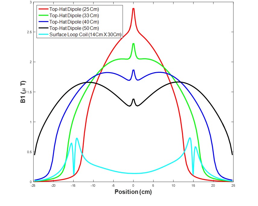
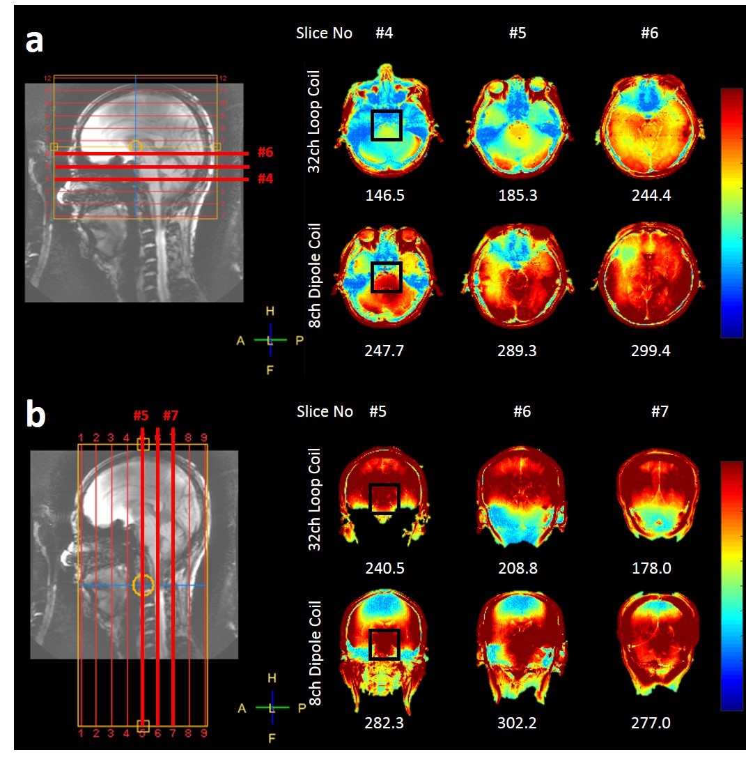
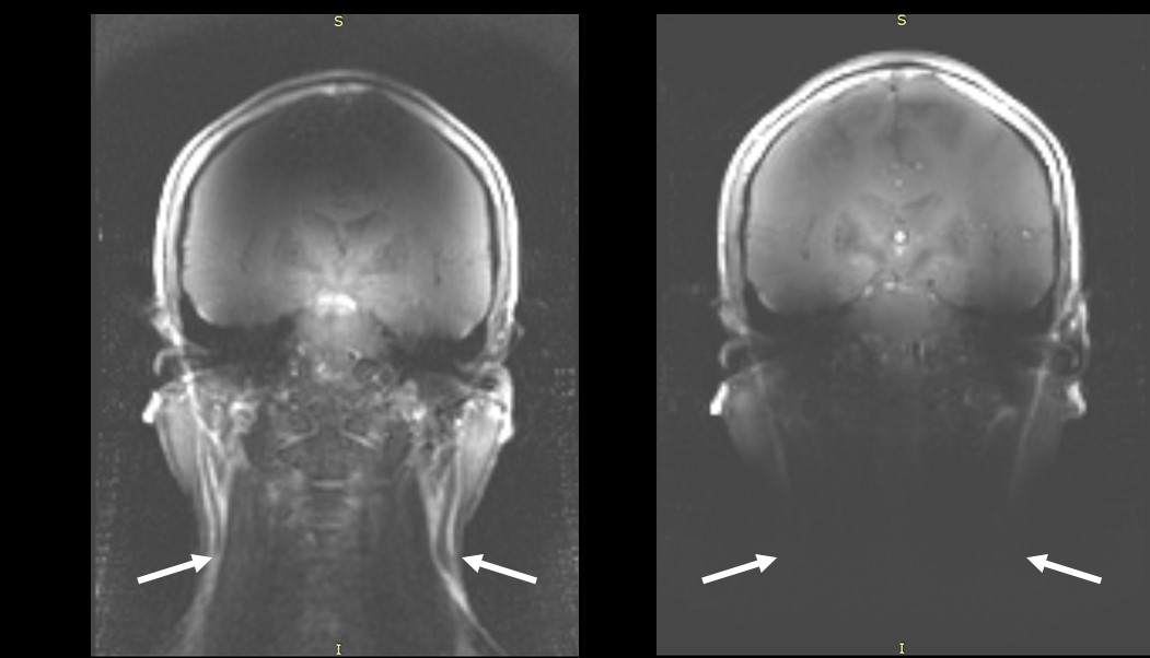
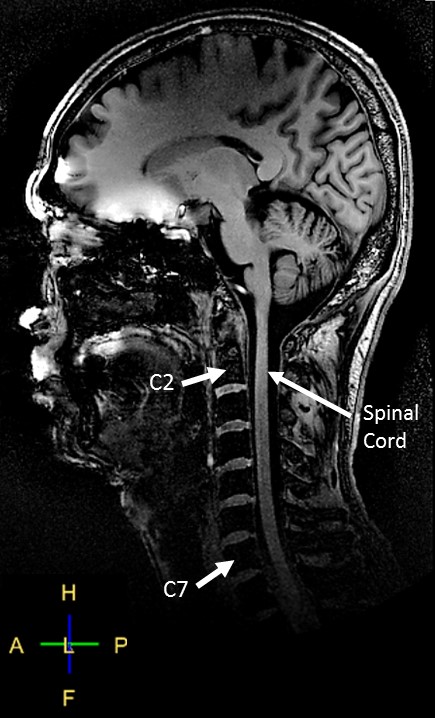
Figure 2 shows the simulation results of the B1 profile for different lengths of top-hat dipole antenna, showing that there is an optimal length for the best B1 uniformity depending on the RIOs in the z-direction. The SNR for the axial images are compared for the two coils in Fig. 3(a). The SNR of 8-channel top-hat dipole coil is about 1.5 times higher than surface loop coil at the central region of interest (ROI). In case of coronal images (Fig. 3(b)), the SNR at central ROIs of the images from the dipole RF coil is about 1.32-times of that from the loop coil while the dipole RF coil has low SNR in upper region of the brain. Figure 4 shows the coronal images acquired with an identical FOV and display window for the two coils, showing the imaging FOV and SNR difference. Figure 5 shows one of the sagittal images acquired using the dipole coil. The whole cervical vertebrae area can be clearly seen in the figure.DISCUSSION AND CONCLUSION
An 8-channel top-hat dipole coil is proposed for whole brain imaging at 7 T MRI. Although the SNR of the images for the upper region of the brain is higher for the 32-loop-element RF coil than for the 8-channel top-hat dipole coil, the proposed top-hat RF coil has an advantage of the imaging coverage in the inferior region of the brain. Figure 5 shows the whole brain image including the cervical spine up to C-7 section of the cervical vertebrae. In addition, the top-hat dipole RF coil has less complexity and coupling problem in constructing the coils compared to the 32-loop-element RF coil.Acknowledgements
This research was supported by the Korea Basic Science Institute under the R&D program (Project No. D36700) supervised by the Ministry of Science, ICT, and Future Planning, the MEST-BMBF University Cooperation Programme: NRF-2012K1A3A1A24025536, and the National Research Foundation of Korea (NRF) grant funded by the Korea government (MSIP) (No. NRF-2016R1C1B2015216).References
[1] Woo, M. K. et al. "Extended monopole antenna array with individual shield (EMAS) coil: an improved monopole antenna design for brain imaging at 7 tesla MRI." Magnetic Resonance in Medicine, 75.5 (2015): 1944-1952.
[2] Kumar, S. et al. “Improved B1+ along z-direction using top-hat dipole antenna pTX array for body imaging at 7 tesla,” ISMRM (2016): 1801.
[3] Sim4Life by ZMT, <http://www.zurichmedtech.com>
Figures