0766
Dielectric resonator antenna receive array at 7 Tesla using detunable ceramic resonators1Radiology, Leiden University Medical Center, Leiden, Netherlands
Synopsis
A receive-only array of dielectric resonator antennas has been developed. A method for detuning the ceramic resonators is studied using simulations and measurements, after which a four-channel dielectric resonator antenna array is used for in vivo image acquisition of the ankle. Using this receive-only array allows for higher SNR and parallel imaging using SENSE.
Purpose
Previous work has shown that dielectric resonators with a high permittivity can be used as an annular transmit/receive coil as well as a transmit-receive array1,2,3. Initial experiments at 7 T using thin materials with a relative permittivity above 1000 showed very little inter-element coupling when used in an array.4 Ideally these type of elements could also be used in receive-only mode in a similar fashion to conventional surface coils. However, this requires that the dielectric resonator be able to be electronically detuned. Although detuning methods for liquid-based dielectric resonators have been presented5, these are not applicable to solid based designs. In this study a method for effective detuning of ceramic based dielectric resonators is shown. In vivo images of the ankle are acquired using a volume coil transmit and dielectric resonator array receive.Methods
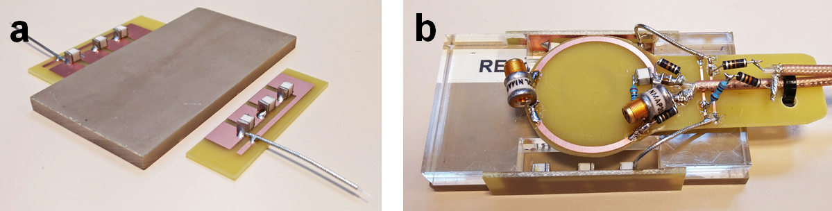
Electromagnetic simulations were performed using the eigenmode solver of CST Microwave Studio (Darmstadt, Germany). Rectangular (88x44x5 mm3) ceramic blocks of lead zirconate titanate (PZT) with a relative permittivity of ~1000, were used to create a dielectric resonator. A small coupling loop placed above the resonator was used to critically couple into the TE01δ mode of the dielectric resonator. The frequency of this mode was measured using a network analyser using a non-resonant pickup loop placed close to the ceramic block. The detuning was implemented by attaching four copper strips (10x10 mm2) to each long side of the resonator using conductive silver paint. This does not influence the resonant mode significantly. These strips are interconnected using PIN diodes and when a current passes through these diodes, the four copper strips act effectively as a single long strip, which produces a large downward frequency shift in the mode. Since the inductive coupling loop (resonant at ~320 MHz) can also interact with the volume coil, it is also detuned using a conventional PIN diode arrangement. In vivo experiments were performed on a human 7 Tesla MRI system (Philips Achieva) on healthy volunteers. Images of the ankle were acquired using a 3D gradient echo sequence (T1 weighted, 160x160x80 pixels, 0.75 mm isotropic spatial resolution, TE 2.8 ms, TR 10 ms, FA 10°, acq. time 168 seconds). For the in vivo experiments a four-channel array was formed from four individual detunable dielectric resonators.Results and discussion
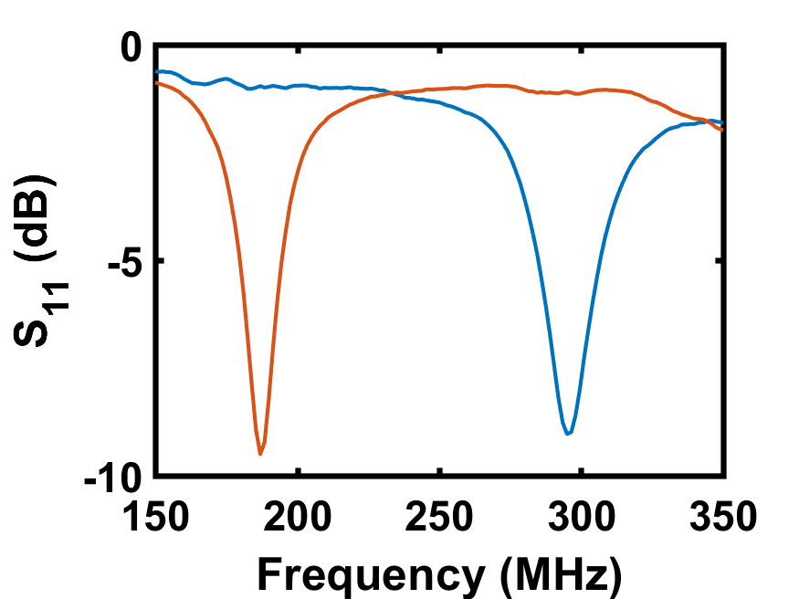
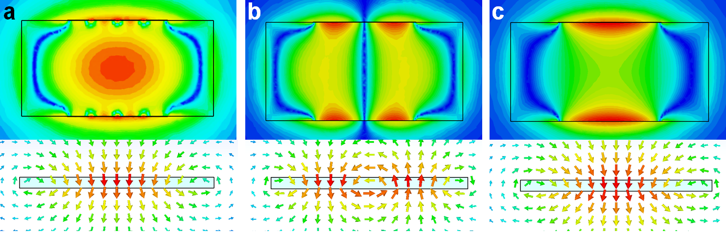
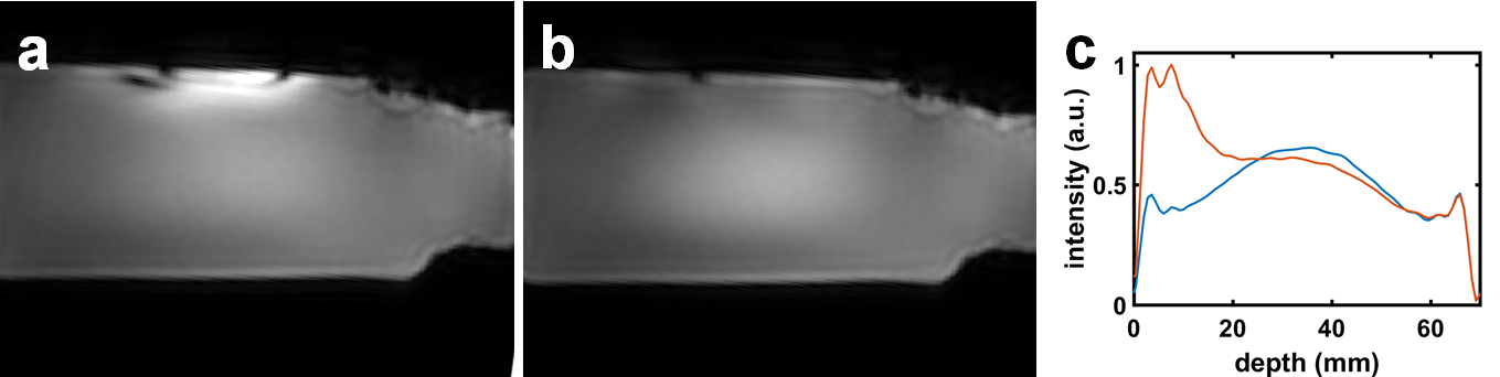
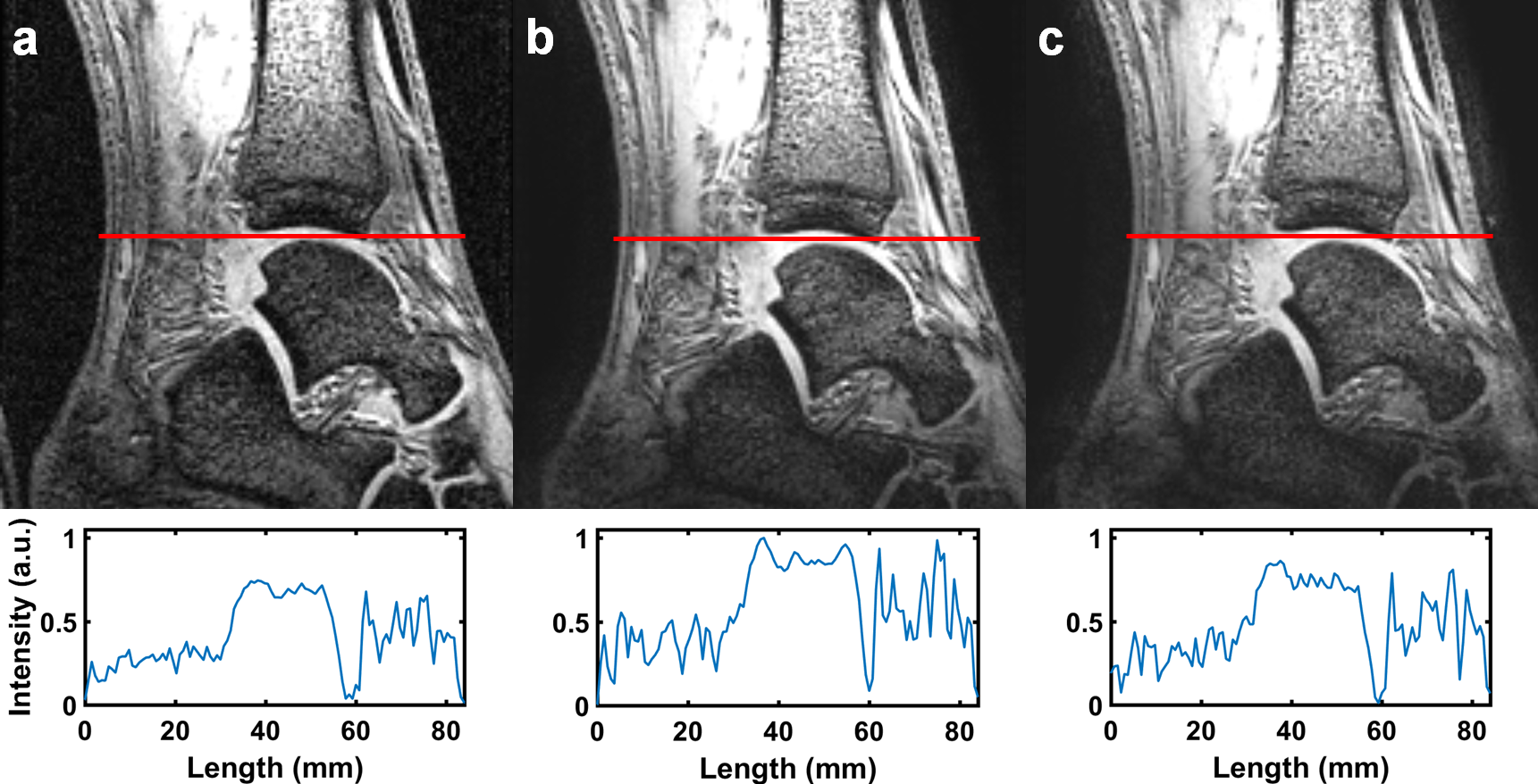
The ceramic block which comprises the dielectric resonator and the detuning circuit are shown in Figure 1(a), and the full set-up with inductive coupling loop in Figure 1(b). The S11 plot of the tuned resonator placed on a loading phantom is illustrated in blue in Figure 2, showing the resonant TE01δ mode at 298 MHz, the B-field of which is shown in Figure 3(a). When a current is passed through the PIN diodes, the resonance shifts by more than 100 MHz to a lower frequency. Although there is a remnant hybrid mode which appears close to 298 MHz, it has a geometry that does not couple into the pick-up loop and so does not contribute any signal, as well as having only a very small component of the magnetic field which is parallel to B0 and so produces no signal. Electromagnetic simulations show that the shifted mode at 190 MHz is also a hybrid. After these bench and simulation test, a phantom scan was performed to show the effectiveness of the detuning design. Figure 4(a) shows an image transmitting and receiving by a volume coil with the tuned dielectric resonator placed next to the phantom: as expected the field is focussed and produces strong over-tipping artefacts. These are eliminated when the dielectric resonator is detuned during pulse transmission, as shown in Figure 4(b).The four-element receive-only array consisting of four individual detunable dielectric resonators was placed inside a volume birdcage as a transmit element. With this setup, in vivo images were acquired of the ankle of a healthy volunteer. These images were compared to images acquired using the volume birdcage coil in both transmit and receive. The images acquired with the DRA array show a higher SNR due to their high local sensitivity, as can be seen in Figure 5. Accelerated imaging using SENSE was also performed with no artefacts from coil coupling present.
Conclusion
Detuning of dielectric resonators in dielectric resonator antennas is essential for a receive-only array. In this work a method for detuning of such resonators is presented. In vivo receive-only imaging with the detunable dielectric resonators show an increased SNR with respect to transmit-receive imaging with a volume coil.Acknowledgements
This work was funded by the NWO-STW, grant number 13783References
1. Wen H., et al., ‘The evaluation of dielectric resonators containing H2O or D2O as RF coils for high-field MR imaging and spectroscopy’, J. Magn. Reson. Ser. B, 1996, 110.2: 117–123. 2.
2. Aussenhofer S.A. and Webb A.G.,’An eight-channel transmit/receive array of TE 01 mode high permittivity ceramic resonators for human imaging at 7T’, J. Magn. Reson., 2014, 243:122–129
3. Lu J.Y., et al., ‘A novel 7 T transmit array using TE01d mode dielectric resonators’, 2013, Int. Soc. Magn. Reson. Med., 4376
4. O’Reilly T., et al., ‘Modular 7 Tesla transmit/receive arrays designed using thin very high permittivity dielectric resonator antennas’, 2016, Int. Soc. Magn. Reson. Med., 0393 5.
5. Aussenhofer S.A. and Webb A.G., ‘Design and evaluation of a detunable water-based quadrature HEM11 mode dielectric resonator as a new type of volume coil for high field MRI.’, 2012, Magn. Reson. Med., 68.4:1325-1331
Figures