0764
Resonance frequency detection of a stretchable RF receiver coil for MRI1Electronics Laboratory, ETH Zurich, Zurich, Switzerland, 2Integrated Systems Laboratory, ETH Zurich, Switzerland
Synopsis
Wearable RF receiver coils change their resonance frequency when stretched or bent. We propose a system that detects this change in resonance frequency. The system is integrated on a wearable MRI receiver of 20 x 30mm². The change in resonance frequency can be detected in-field. The detection works by sweeping an excitation current through a frequency range and measuring the frequency response. The frequency response is transmitted via a glass fibre to an out-field signal processing unit. Measurements were conducted using a stretchable liquid metal coil on neoprene.
Introduction
Wearable and conformal radio-frequency (RF) receiver coils promise more patient comfort, better image quality and more freedom in limb positioning during magnetic resonance imaging (MRI)1. However, bending and stretching of the receiver coils change the resonance frequency of the coil and thus introduce losses. To counteract this frequency shift, the resonance frequency has to be detected and compensated. An integrated CMOS receiver was previously developed by Sporrer et al. to bring the data conversion in-field and close to the signal source2. To minimize coupling and distortion due to metallic cables, data is transferred from and to the receiver over a glass fibre link to an out-field signal processor3. We extended the functionality of this wearable MRI receiver to detect shifts in resonance frequency.Methods
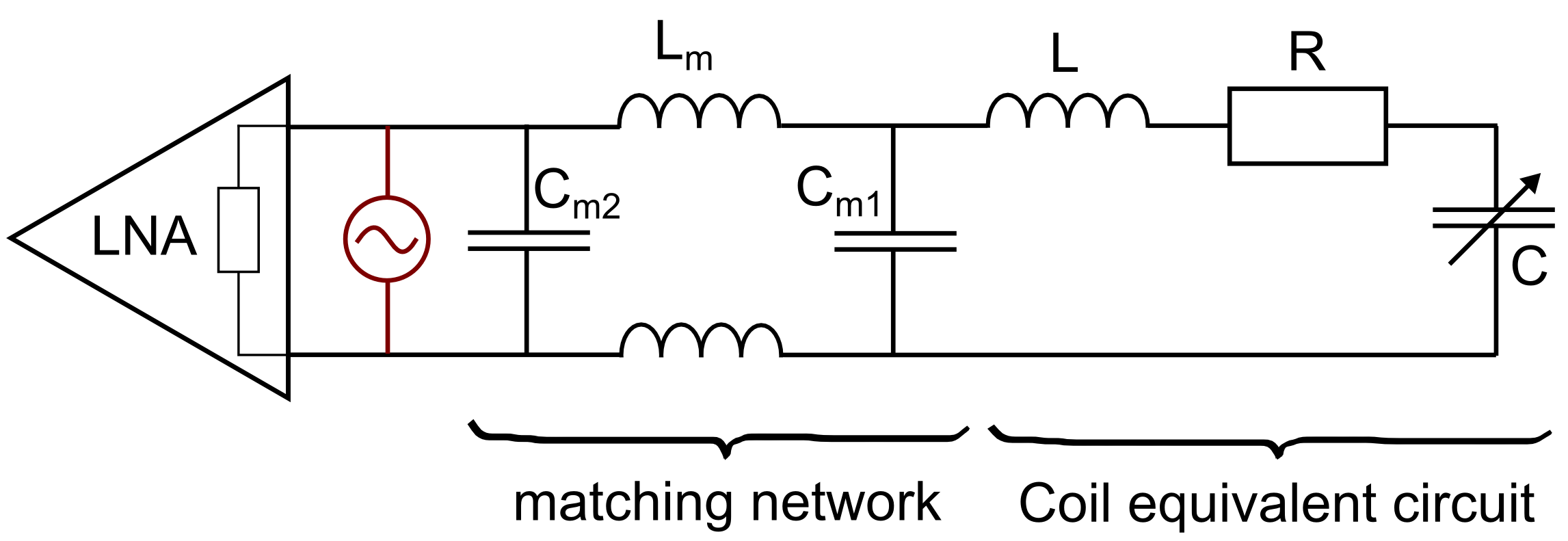
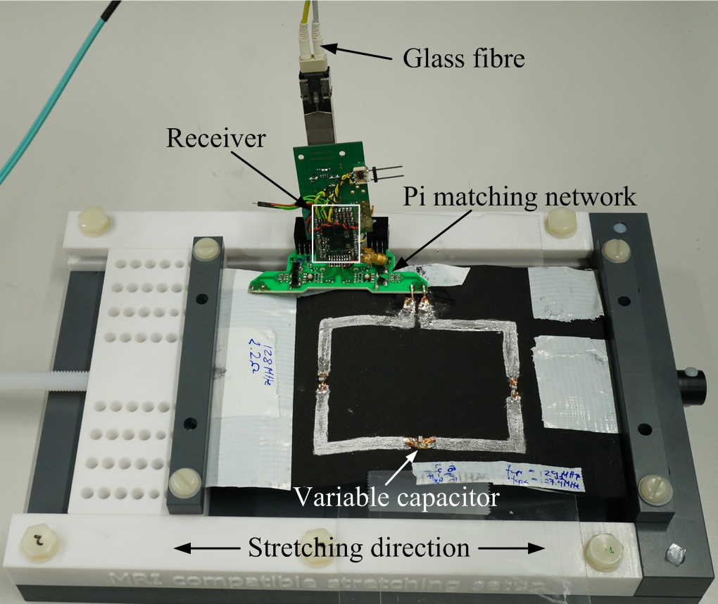
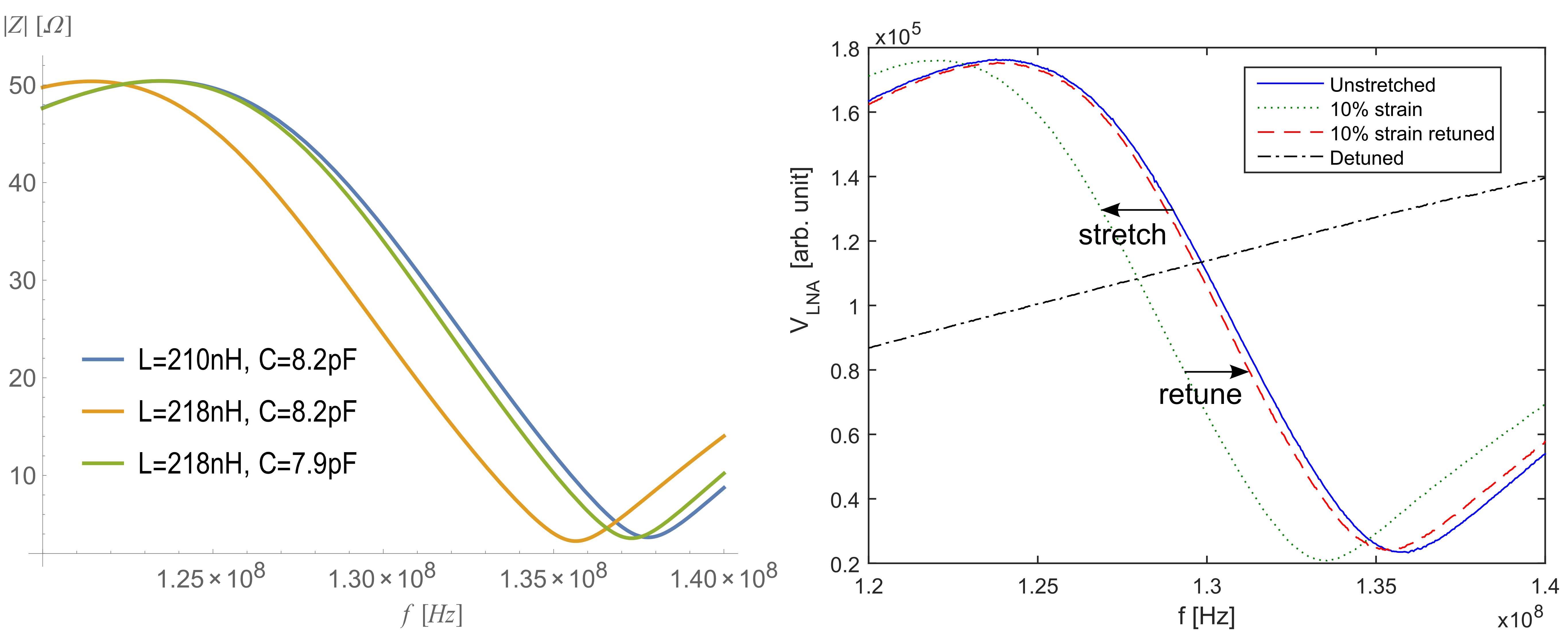
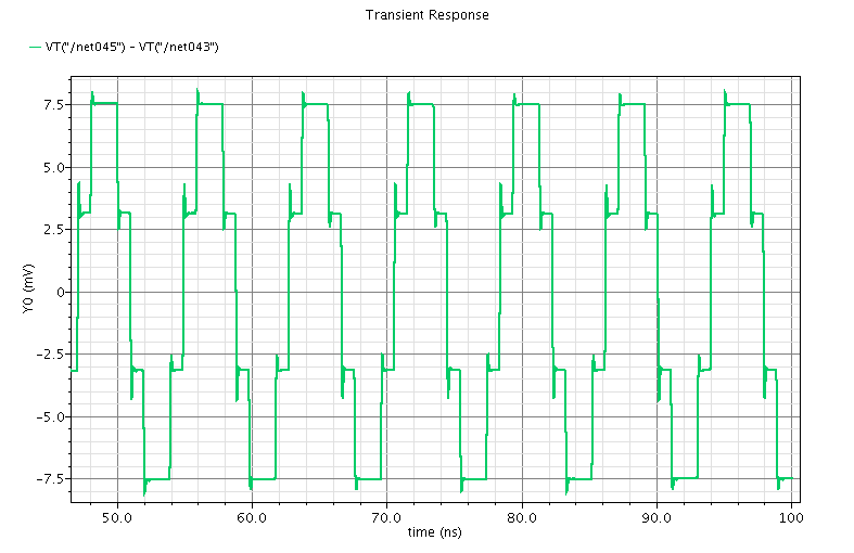
FEM simulations were conducted with HFSS and Comsol to find the inductance of a bent or stretched coil. The resulting inductances were inserted into analytical calculations to find the dependence of the resonance frequency on the inductance and therefore on the bending radius or strain. Fig. 1 shows the diagram of the circuit we analysed. The coil was approximated as an RLC series circuit. The impedance of the coil is transformed to 500Ω by a Pi matching network. The input impedance of the low noise amplifier (LNA) is 50Ω. The mismatch was chosen to prevent mutual coupling in future array applications. Analytical calculations were conducted to find the impedance at the input of the LNA. The inductance was changed from 210nH to 218nH, corresponding to stretching a 86 x 70 mm² rectangular coil by 10%. This requires the RLC series capacitance C to change from 8.2pF to 7.9pF to restore the original resonance frequency. Simulations and analytical calculations were validated by measurements of a stretchable liquid metal coil on neoprene. The resonance frequency of the liquid metal coil was 121MHz. To detect the resonance frequency with the wearable MRI receiver, the front-end of the receiver was adapted to excite the coil with a direct digitally synthesised sinusoidal current of variable frequency. The setup is shown in Fig. 2. The coil can be stretched and thus changes its resonance frequency. The current source is depicted in Fig. 1 and Fig. 4 shows a simulation of the output current. The output current generated by the receiver can be varied between 20 and 300µA. The resulting voltage at the LNA input was measured with the receiver. The receiver down-converts the input signal into base-band. The excitation current was swept through a frequency range of 120MHz to 140MHz. The measurements in this work were conducted with 20µA, since higher currents drove the LNA into saturation with the given matching network and coil. The filtering of the receiver output is done on the wearable device to reduce noise picked up by the coil. An FPGA on the wearable MRI receiver board low-pass filters and down-samples the baseband signal coming from the receiver. The filtering is done using a CIC decimator (15MHz to 15kHz) and a cascaded 4th order IIR LP filter with a cut-off frequency of 0.7kHz. The frequency sweep was divided into 500 steps. After each frequency alteration, a 250ms pause allowed the ringing to stabilise, after which a filtered data sample was acquired. The different samples at each frequency form the frequency response. The excitation frequency and the frequency response were transmitted over the glass fibre link.Results
The measurement results of the network analyser (HP 8753E) and the wearable receiver agree with the analytical calculations. The resonance frequency shift can be detected by a shift of the peak of the frequency response at the LNA input. Bending and stretching of the coil result in a frequency shift of the peak. This shift can be counteracted by changing the variable capacitance on the coil, see Fig. 3. The frequency shift of about 2.5MHz when stretching by 10% corresponds to the resonance frequency measurements of the coil when stretched by 10% without a matching network.Discussion
We have developed a system which can detect shifts in resonance frequency in-field. While the position of the peak is not equal to the resonance frequency due to mismatch between the receiver and the matched coil, the original position of the peak can be used as reference which has to be restored.Conclusion
Our system allows to detect the change in resonance frequency of a stretchable coil. While the resonance shift due to stretching was counteracted manually by turning a variable capacitor, future research will be dedicated to detecting the peak position and changing the capacitance automatically.Acknowledgements
This research is funded by the Swiss Nano-Tera project WearableMRI.References
1. Corea J., et al., Screen-printed flexible MRI receive coils, Nature Communications, 2016.
2. Sporrer B., et al., Integrated CMOS Receiver for Wearable Coil Arrays in MRI Applications, DATE, 2015.
3. Brunner D., et al., Receive Array Design with On-Coil Digital Receiver, ISMRM, 2016.
Figures