0763
Characterization of a new ultra-flexible, low profile RF receive coil technology.1Department of Radiology, Mayo Clinic, Rochester, MN, United States, 2GE Healthcare, Waukesha, WI
Synopsis
A new highly flexible RF coil design is described. Individual coil elements are constructed by means of a proprietary process that yields low reactance and low loss conductors while being lightweight, flexible, and durable. Phantom data indicate that for similar coil geometries, the coils provide equivalent SNR profiles but do not suffer from design limitations due to minimum coil overlap requirements of conventional copper coil elements. In vivo data demonstrate that these coils can be fabricated onto highly flexible and thin support materials that closely comply with anatomic contours in challenging imaging sites such as the c-spine.
Introduction
Historically, the design and manufacture of copper based, series lumped element receive-only RF coils has focused on durability and physical strength. However, this has resulted in the creation of large, heavy and inflexible coils that are difficult to place close to the patient. With the growth of MR for non-traditional applications such as interventional MR, interoperative MR and MR for radiation therapy planning there is a need for highly flexible, thin (small form factor) and physically robust RF coils that can be placed on and around an individual patient’s anatomy1. The purpose of this work is to characterize a new, highly flexible RF coil design to meet these as yet unmet needs.Methods
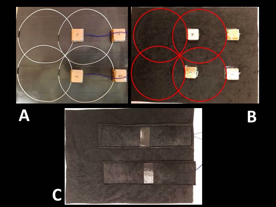
RF Coil design: One, two and four element ‘AIR Tech’ (GE Healthcare, Waukesha, WI) receive-only RF arrays were constructed. The diameter of each element was fixed and equal to 11 cm and included an associated microelectronic tuning circuit. Individual loops are manufactured using a proprietary process that yields low reactance and low loss conductors, while being exceptionally lightweight, flexible, and durable. Figure 1 shows a four element array and associated miniaturized supporting electronics. A unique feature of this coil design is that the conductor and electronics combination serve to control inter loop interactions. This allows for coil loop overlaps2 that could not be achieved with conventional copper-based elements without the introduction of artifacts and significantly reduced signal-to-noise ratio (SNR).
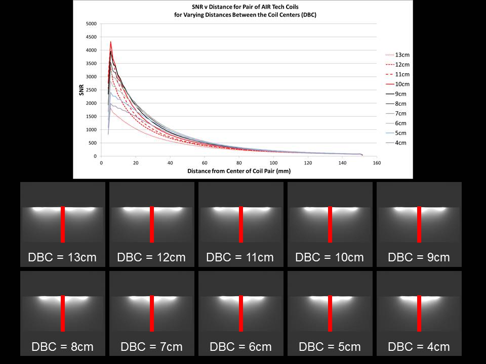
Phantom experiments: All experiments were conducted on a 3.0T whole body 60 cm bore diameter MR scanner (Signa EXCITE 16.0, GE Healthcare). An electrically non-loading doped rectangular silicone phantom was used to collect SNR and signal intensity profile data. Measurements were obtained using a T1-weighted spin echo pulse sequence (TE/TR = 15 msec/750 msec, FOV = 32 cm, slice thickness = 5mm, signal averages = 1, matrix = 256 x 256 : frequency x phase). Data was collected from double loop coil configurations (Figure 2) and compared to a pair of traditionally constructed coils at the nominal coil center to center distance (86 mm). Data were also collected with the AIR Tech coils over a range of coil center spacings.
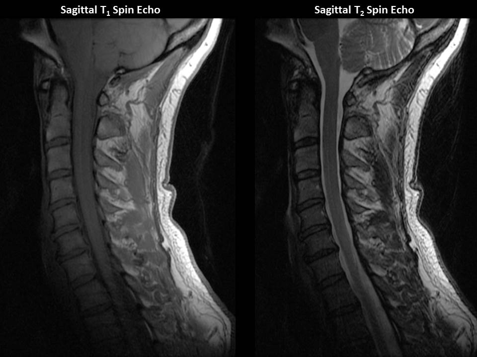
In vivo experiments: The four channel array shown in Figure 1 was used for in vivo data collection. 3T (Signa EXCITE 16.0, GE Healthcare) T1- (TE/TR = 9 msec/750 msec, matrix = 352 x 256 : frequency x phase, FOV = 22 cm, slice thickness = 3.5 mm, signal averages = 1, echo train length = 3) and T2-weighted (TE/TR = 107 msec/3200 msec, matrix = 384 x 256 : frequency x phase, FOV = 22 cm, slice thickness = 3.5 mm, signal averages = 1, echo train length = 23) multi echo spin echo images were acquired in both axial and sagittal planes from two normal volunteers. The array was placed underneath the necks of the volunteers resulting in physical coverage of the array from skull base to approximately the C7 vertebral body. The coil was wrapped around the sides of the neck of each volunteer and reached approximately mid line for both.
Results
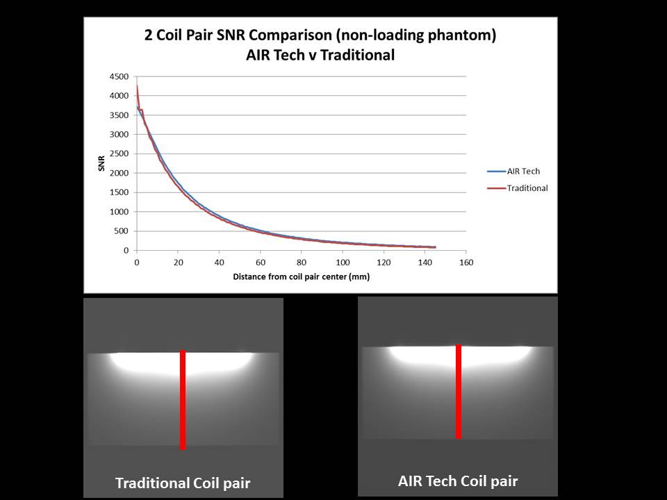
Figure 3 shows the signal intensity images and SNR plots for a overlapped pair of traditional and AIR Tech coil elements. At the same center-to-center spacing the coils provide similar performance characteristics. For traditionally constructed coil loops, the optimal center-to-center distance (i.e. that which results in minimal intra loop interaction) for this size loop is 86 mm. Figure 4 shows the signal intensity and SNR plots for a pair of AIR Tech coils elements with different center-to-center distances. Figure 5 shows sagittal image data from the second normal volunteer. Despite the absence of any coil elements anterior to the subject’s anatomy, diagnostic quality data were obtained.Discussion
Phantom data demonstrate that for a given coil diameter, both conventional (i.e. copper) and AIR Tech coils produce SNR values that are identical. However, the advantage of the later coil is the removal of the design restriction of minimum overlap between individual coil elements in addition to their compact form and flexibility. In vivo data demonstrate that the technical advantages of the AIR Tech coil technology can have direct clinical translation.Conclusion
AIR Tech coil technology has the potential to provide high density, low profile and extremely flexible RF coils for a variety of uses including interoperative MR, interventional MR, MR for radiation therapy planning and other clinical applications.Acknowledgements
No acknowledgement found.References
1. K.P. McGee, Y. Hu, E. Tryggestad, D. Brinkmann, B. Witte, K. Welker, A. Panda, M. Haddock, M.A. Bernstein, "MRI in radiation oncology: Underserved needs," Magn Reson Med 75, 11-14 (2016).
2. P.B. Roemer, W.A. Edelstein, C.E. Hayes, S.P. Souza, O.M. Mueller, "The NMR phased array," Magnetic Resonance in Medicine 16, 192-225 (1990).
Figures