0762
Development and performance evaluation of the second prototype of a RF-coil integrated PET insert for existing 3T MRI systems1National Institute of Radiological Sciences, Chiba, Japan, 2Chiba University, Chiba, Japan, 3Hamamatsu Photonics K.K., Hamamatsu, Japan
Synopsis
We developed an RF-coil integrated DOI-PET insert for the 3T MRI system for human brain imaging. In this study we have given details of the second prototype system developed recently and evaluated performance for MRI-only, PET-only and simultaneous PET/MRI conditions. This system included 24 carbon fiber shielded PET modules which are positioned in between the coil-elements of a birdcage head-coil. In total 48 4-layer DOI detectors are included that gives 60 mm axial-FOV for PET imaging. Under all performance study the system worked quite well showing promise for near-future human brain study.
Introduction
PET inserts for the existing MRI systems [1-3], especially for human brain imaging, are emerging as a potential affordable low-cost multimodality imaging tool that would otherwise provide high sensitivity in PET imaging due to proximity of detectors near the imaging region. For high PET resolution even near the detectors and to avoid parallax errors [2,4], information of the depth-of-interaction (DOI) of gamma-ray in the scintillation crystal is a prime need.
We developed 4-layer DOI capable PET detectors integrated with RF birdcage head-coil in which the PET detectors are positioned in between the coil elements to make the detectors as close to the imaging region as possible. In [5] we proposed our first prototype model with small-scale design for feasibility study in which two of the eight PET modules were mounted with DOI-PET detectors. Recently we have developed a complete PET-ring insert with 24 DOI-PET modules that are integrated with an 8-element birdcage coil. This study includes details of the development and, PET and MRI studies of this module with a 3T clinical MRI system.
System Development
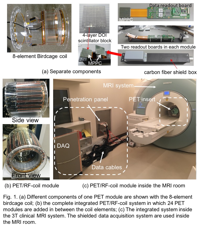
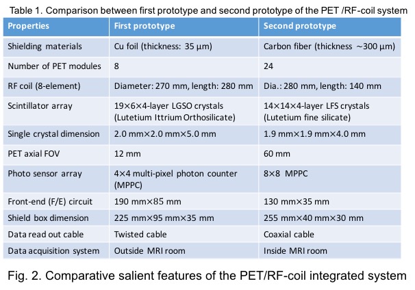
The photographs of different important components and complete integrated PET/RF-coil system with clinical 3T MRI system (Siemens MAGNETOM Verio) are illustrated in Fig. 1. Compare to the first prototype we have made several improvements in this large-scale second prototype which are comparatively tabulated in Fig. 2. The improvements include:
1. carbon-fiber shielded Faraday cages for better RF-shielding with reduced eddy current
2. smaller DOI-crystal elements for better image resolution
3. large PET axial-FOV (60mm) by mounting two ring PET detector modules (in total 48 detectors) for human brain study
4. ASICs in the PET readout board for accurate pre-amplification of raw PET data
5. MPPCs (pixel size of 50μm × 50μm (HAMAMATSU S12641PA-050)) with a temperature sensor to limit gain fluctuation by changing high-voltage supply using a microprocessor controlled feedback [5]
6. PET signal processing unit is installed inside the MRI room (Fig. 1(c)) for better SNR and so on
24 carbon-fiber shielded PET modules are arranged in between the eight elements of a custom-designed birdcage coil of diameter 280mm and axial-length 140mm. In each PET modules we mounted two PET detectors – that means, two 14X14X4-layer LFS-scintillation blocks, two MPPCs and two readout front-end (F/E) boards in each shielded module. The complete system was optimized for using with a 3T clinical MRI system installed in our institute.
Evaluation methods
The S-parameters of the RF coil was studied with a network analyzer (ROHDE & SCHWARZ ZVL) considering the integrated system inside the MRI bore with phantom.
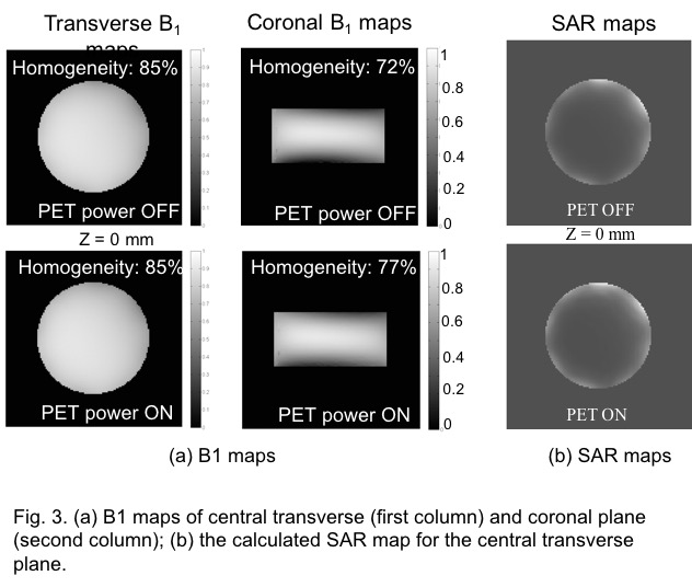
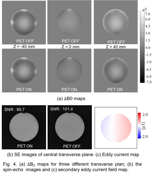
The B1 field, B0 inhomogeneity, eddy currents and SAR calculation were conducted for a cylindrical homogeneous phantom of diameter 200mm and axial-length 100mm. For B1 we implemented double-angle method [6-7], for B0 we implemented phase difference method [8] and for eddy currents we implemented EPI phase correction approach [9]. Local SAR was calculated from B1 map by electric properties tomography (EPT) approach [10]. All of the measurements were conducted for both PET detectors power-ON and power-OFF conditions.
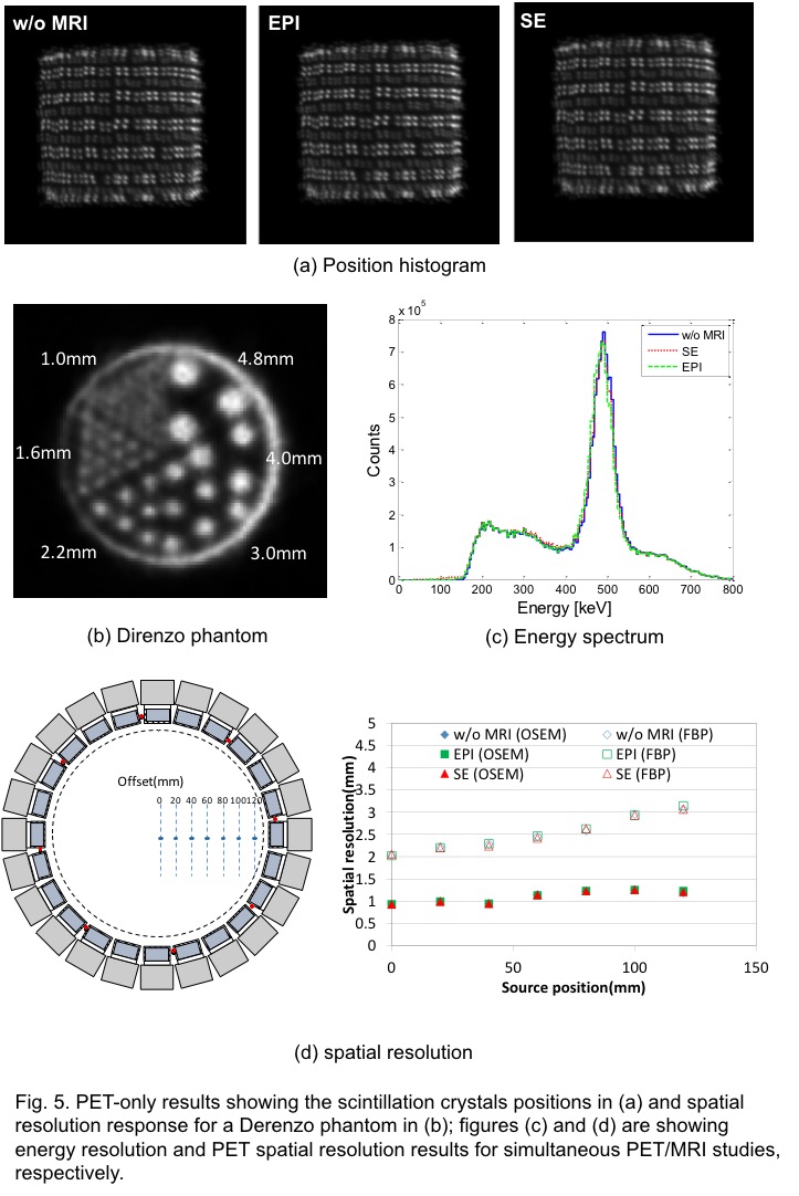
In case of PET, we measured scintillator position detection after calibration done for each block. The position histogram and energy spectrum were measured for without (w/o) MRI and, PET-ON with spin-echo (SE) and echo-planar (EPI) sequences. The spatial resolution was measured in a radiation controlled room for a Derenzo phantom and also inside the MRI-bore for a point source positioning at different positions along the radial direction for w/o MRI and, SE and EPI sequences.
Results
The S11 parameter was -25dB. The results of B1 field for the central transverse and coronal planes are illustrated in Fig.3(a). In the transverse map we found no change though a 5-percentage point increased homogeneity was seen in coronal map. Fig.3(b) are showing SAR maps that are calculated from the transverse B1 maps shown Fig.3(a). The maximum B0 inhomogeneity was about 2ppm as is illustrated in Fig.4(a). About 1ppm increase was seen for PET-ON compare to PET-OFF. The SE images with SNR values and measured eddy current fields are given in Fig.4(b) and Fig.4(c).
The PET-only measurement results for scintillation crystal position histogram and spatial resolution for Derenzo phantom are given in Fig.5(a)-(b). Spatial resolution of 1.6mm was clearly seen for PET phantom imaging. Also MRI effect on PET energy spectrum and spatial resolution for two different PET-reconstruction approaches are given in Figs.5(c) and (d), respectively.
Conclusion
Under all experimental study, the integrated PET/RF-coil modality was found to response quite well with high spatial resolution and high sensitivity. It shows promise for near future investigation for simultaneous PET/MRI human brain study.Acknowledgements
This study was funded by the Japanese government grants: KAKENHI (No. 24390295), Japan Science and Technology Agency (JST) and Japan Agency for Medical Research and development (AMED).References
[1] A. Kolb, H.F. Wehrl, M. Hofmann, et al., Technical performance evaluation of a human brain PET/MRI system, Eur. Radiol. 22 (2012) 1776–1788. doi: 10.1007/s00330-012-2415-4
[2] F. Nishikido, T. Obata, K. Shimizu, et al., Feasibility of a brain-dedicated PET-MRI system using four-layer DOI detectors integrated with an RF head coil, Nucl. Instr. Meth. Phys. Res. A 756 (2014) 6–13. http://dx.doi.org/10.1016/j.nima.2014.04.034
[3] P. Olcott, E. Kim, K. Hong, et al., Prototype positron emission tomography insert with electro-optical signal transmission for simultaneous operation with MRI, Phys. Med. Biol. 60 (2015) 3459–478. doi: 10.1088/0031-9155/60/9/3459
[4] T. Tsuda, H. Murayama, K. Kitamura, et al., A four-layer depth of interaction detector block for small animal PET, IEEE Trans. Nucl. Scien. 51 (2004) 2537–2542. doi: 10.1109/TNS.2004.835739.
[5] K. Shimizu, K. Hakamata, T. Sakai, et al., Multi-pixel photon counter module for MRI compatible application, IEEE NSS/MIC (2015) M3CP-85.
[6] R. Stollberger, P. Wach, G. McKinnon, et al., RF field mapping in vivo, Abstracts of the Society of Magnetic Resonance in Medicine, 7th Annual Meeting (1988) p.106.
[7] E.K. Insko, L. Bolinger, Mapping of radiofrequency field, J. Magn. Reson. Series A 103 (1993) 82-85.
[8] J.G. Och, G.D. Clarke, W.T. Sobol, et al., Acceptance testing of magnetic resonance imaging systems, Med. Phys. 19 (1992) 217-229. doi: 10.1118/1.596903.
[9] M. H. Buonocore, L. Gao, Ghost artifact reduction for echo planar imaging using image phase correction, Magn. Reson. Med., 38 (1997) 89-100.
[10] U. Katscher, T. Voigt, C. Findeklee, et al., Determination of electric conductivity and local SAR via B1 mapping, IEEE Trans. Med. Imaging 28 (2009) 1365-1374. doi: 10.1109/TMI. 2009.2015757.
Figures