0761
Wireless coil based on meta-technologies for MRI implementations1Department of Nanophotonics and Metamaterials, ITMO University, St.Petersburg, Russian Federation, 2Nonlinear Physics Center, Research School of Physics and Engineering, Australian National University, Canberra, Australia, 3Department of Radiology, Leiden University Medical Center, Leiden, Netherlands
Synopsis
We demonstrate experimentally how to improve the performance of MRI by employing wireless coil based on a hybrid tunable metasurface. We fabricate metasurface formed by an array of nonmagnetic metallic wires with high permittivity dielectric loads and investigate it in 1.5 T MRI machine. The metasurface enhances the SNR value in more than 7 times in the region of interest in comparison with the birdcage coil and 2 times versus the dedicated flat local coil.
Introduction
Several studies have suggested that metamaterials can be used to tailor the distribution of electromagnetic fields in MRI1-4. Recent work5 demonstrated a novel approach to achieve the substantial enhancement of the local transmit efficiency with a metasurface structure, which is a two-dimensional realization of a metamaterial6. However, this type of structure is not straightforward to transfer to real clinical MRI systems due to its large size. Another drawback of this previous design is the sinusoidal distribution of the RF magnetic field along its length that resulted in an inhomogeneous SNR enhancement in the region of interest. In this current work, we present a novel metasurface that consists of thin wires loaded by a high-permittivity dielectric slab. We demonstrate that such a hybrid metasurface produces a homogeneously enhanced local magnetic field by a factor-of-three at 1.5 T.Methods
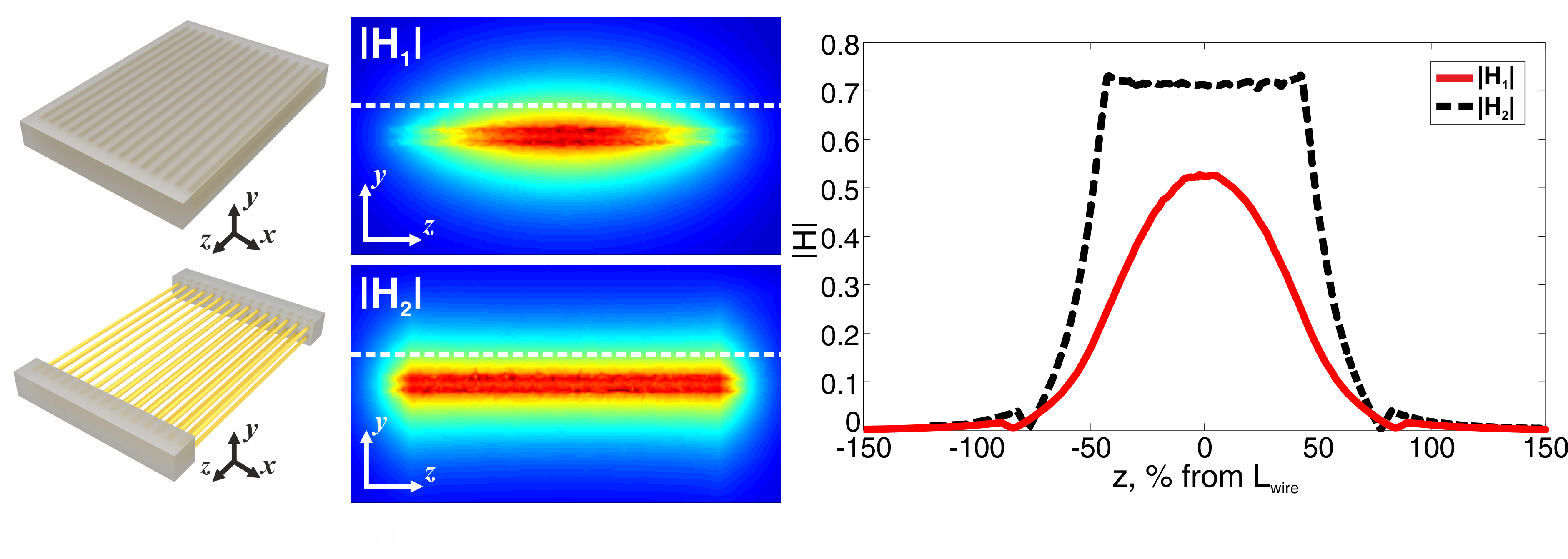
Figure 1 shows a comparison between two metasurface designs: the top left and centre panels correspond to the metasurface from a previous study5 realized by an array of 14x2 brass wires placed inside a homogeneous dielectric medium, whereas the bottom one corresponds to the new hybrid metasurface design realized by brass wires coupled to two high-permittivity dielectric slabs at both sides. For this proof-of-concept study, we use distilled water as a dielectric media with a permittivity of 78 and conductivity of 5.5·10-6 S/m. Tunability is controlled via the effective permittivity around the metasurface (Figure 2). The structure was designed to have approximately the same dimensions as the full imaging field-of-view of the 1.5 T scanner and so has dimensions 38.4x54.8 cm and a height of 20 cm. Numerically calculated magnetic field amplitudes excited by a plane wave (centre panel) are obtained by using the FEM solver in commercially available software (CST Microwave Studio 2015). MR images of a phantom and a grapefruit were acquired on Siemens Magnetom Espree 1.5 T MRI system. The commercial body coil is used for RF transmission and in one case also for signal detection: for SNR measurements a dedicated 4-channel flex coil was used for RF signal detection. A standard gradient-echo sequence was used and the RF power level was adjusted in each case to obtain the maximum signal. The SNR is calculated by dividing a mean value of the signal from the region of interest by the standard deviation of noise in a signal-free region.Results
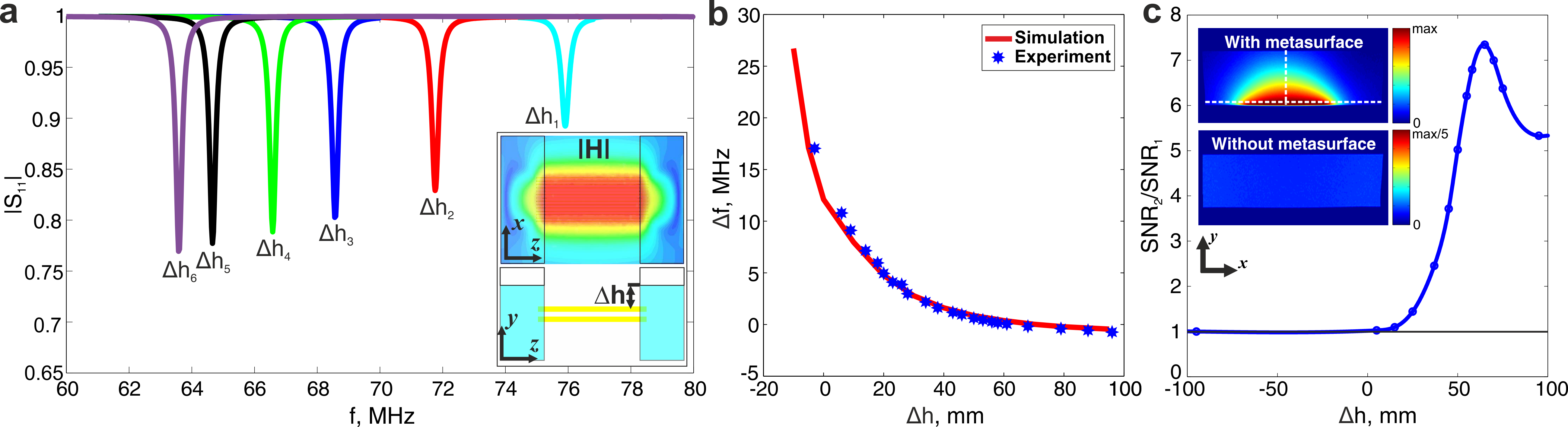
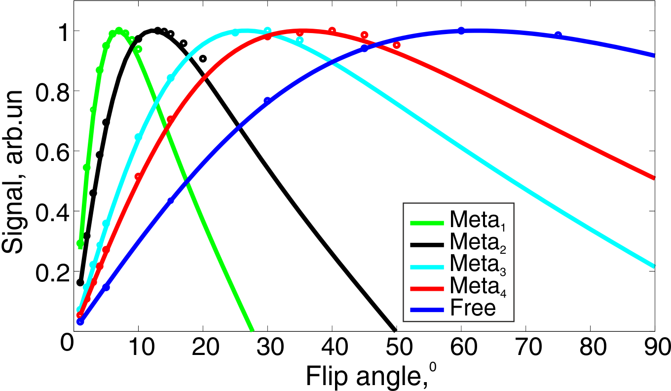
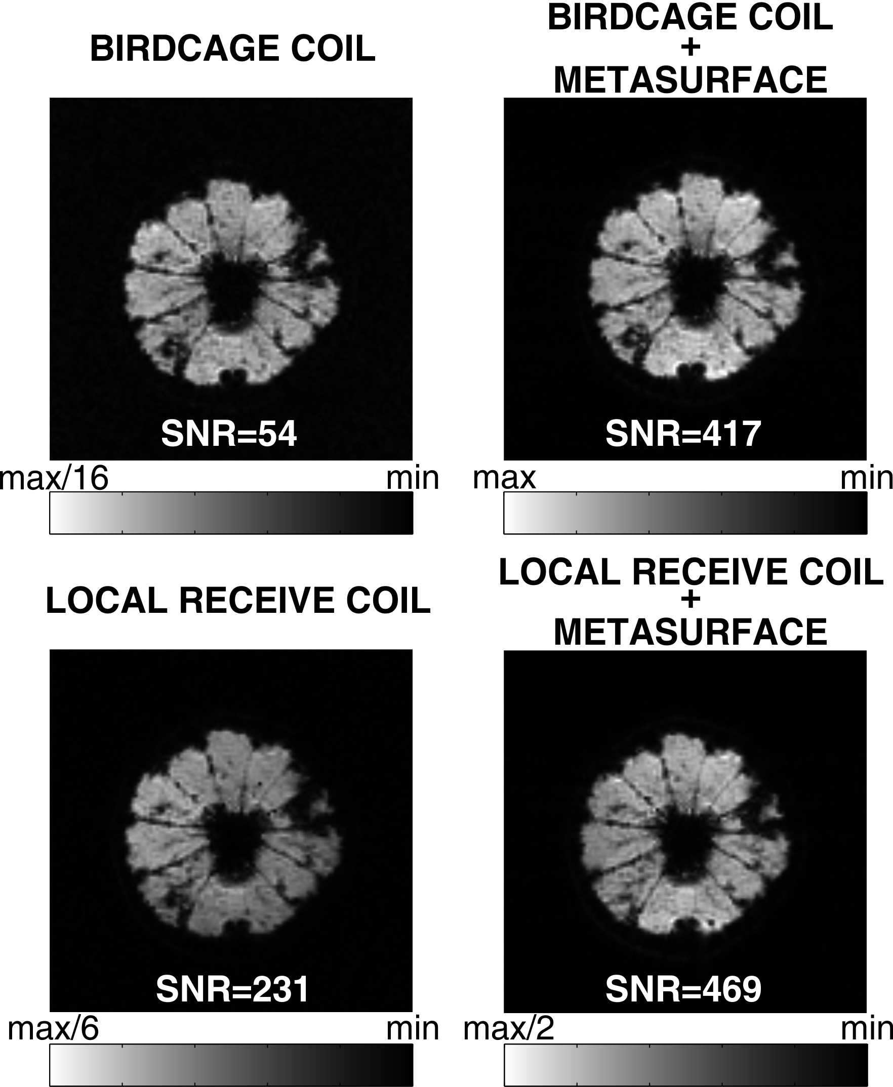
Figure 1 demonstrates the magnetic near-field profile of the eigenmode of the hybrid metasurface calculated at the distance of 2 cm above the wires. The mode has a pronounced flat profile in comparison with a sinusoidal form from a previous realization. Figure 2(a) shows numerical simulations of a hybrid metasurface with a water phantom placed on top of it, and the plots (b,c) present experimental data of the resonance frequency tuned by changing the effective permittivity of the dielectric slab as well as an estimate of the SNR (assuming a body coil transmit and receive, i.e. SNR proportional to the product of B1+ and B1-) for different adjustments of the resonance frequency. The maximum SNR enhancement of 7.34 is achieved for Δh=65 mm. Figure 3 shows MRI signal dependence on the flip angle. Experimental data fits well the theoretical equation: Signal=ρ(r)∙B1-(r)∙e-TE/T2*(1-e-TR/T1)∙sinθ/(1-e-TR/T1∙cosθ), where θ= λ(r )∙θnominal. MR images of a grapefruit are shown in Figure 4.Conclusions
We have suggested and studied experimentally a new design of hybrid metasurface designed to operate at 1.5 T. The metasurface acts as a wireless coil enhancing the SNR value in more than 7 times in the region of interest in comparison with the birdcage coil and 2 times versus the dedicated flat local coil. It also provides an opportunity to obtain a homogeneously enhanced RF magnetic field pattern in the area of interest. It is worth noting that its eigenmode can be dynamically tuned for a specific frequency of MRI operation even in the presence of different objects, and such a wireless coil can be used for MRI of different nuclei.Acknowledgements
This work was supported by the Russian Science Foundation (Grant 15-19-20054) and partially by MediWise Ltd. The authors thank Prof. Nico van den Berg and Dr Alexander Raaijmakers for useful discussions, Prof. Vladimir Fokin, Dr Alexander Efimtcev and Andrey Sokolov for assistance with MRI experiments.References
1. Wiltshire M C K., et al. Microstructured magnetic materials for rf flux guides in magnetic resonance imaging. Science. 2001;291:849–851.
2. Radu X, et al. Toward a wire medium endoscope for MRI imaging. Metamaterials. 2009;3:90-99.
3. Freire M J, et al. On the applications of micror=-1 metamaterial lenses for magnetic resonance imaging. J. Magn. Reson. 2010;203(1):81-90.
4. Zivkovic I, Scheffler K. Metamaterial Cell for B1+ Field Manipulation at 9.4 T MRI. Proc. Intl. Soc. Mag. Reson. Med., 2014;22,4834.
5. Slobozhanyuk A P, et al. Enhancement of Magnetic Resonance Imaging with Metasurfaces. Advanced Materials. 2016;28:1832–1838.
6. Glybovski S B, et al. Metasurfaces: From microwaves to visible. Phys. Rep. 2016;634:1-72.
Figures