0760
Compact iPRES coil assembly for Magnetic Resonance Fingerprinting1Dept of Radiology, Case Western Reserve University, Cleveland Heights, OH, United States, 2Dept of Radiology, Case Western Reserve University, Cleveland, OH, United States, 3Quality Electrodynamics, Mayfield Village, OH, United States, 4Dept of Radiology, Case Western Reserve University, OH, United States
Synopsis
Magnetic Resonance Fingerprinting (MRF) makes use of spatially and temporally incoherent encoding schemes to produce orthogonal signals from different tissues. Here we present a coil optimized for MRF that integrates parallel receive, excitation, and shimming (iPRES) to provide an ideal method of modulating all three available magnetic fields (B1-, B1+, and ΔB0). In order to be useful in quantitative imaging, an iPRES array must convey these fields accurately, and cost effectively. Here we demonstrate an iPRES coil element with all three field amplifiers located on-coil, providing improved sensitivity and efficiency relative to remote amplifiers.
Purpose
Magnetic Resonance Fingerprinting (MRF) makes use of spatially and temporally incoherent encoding schemes to produce orthogonal signals from different tissues1. The incoherent signals are then matched to a dictionary in order to derive quantitative maps of various parameters (T1, T2, ΔB0, etc). MRF has largely been limited to homogeneous excitations and linear gradient encoding. However the ability of an integrated parallel receive/excitation/shim (iPRES) coil array to temporally and spatially manipulate all three available magnetic fields (B1-, B1+, and ΔB0) may enhance the ability of MRF to differentiate tissues. Previous work has demonstrated the use of a single coil element for all three fields2,3, but with the requisite electronics located remotely. Here we propose a similar approach, but with LNA, RFPA, and current amplifiers all located locally, within the scanner bore.Methods
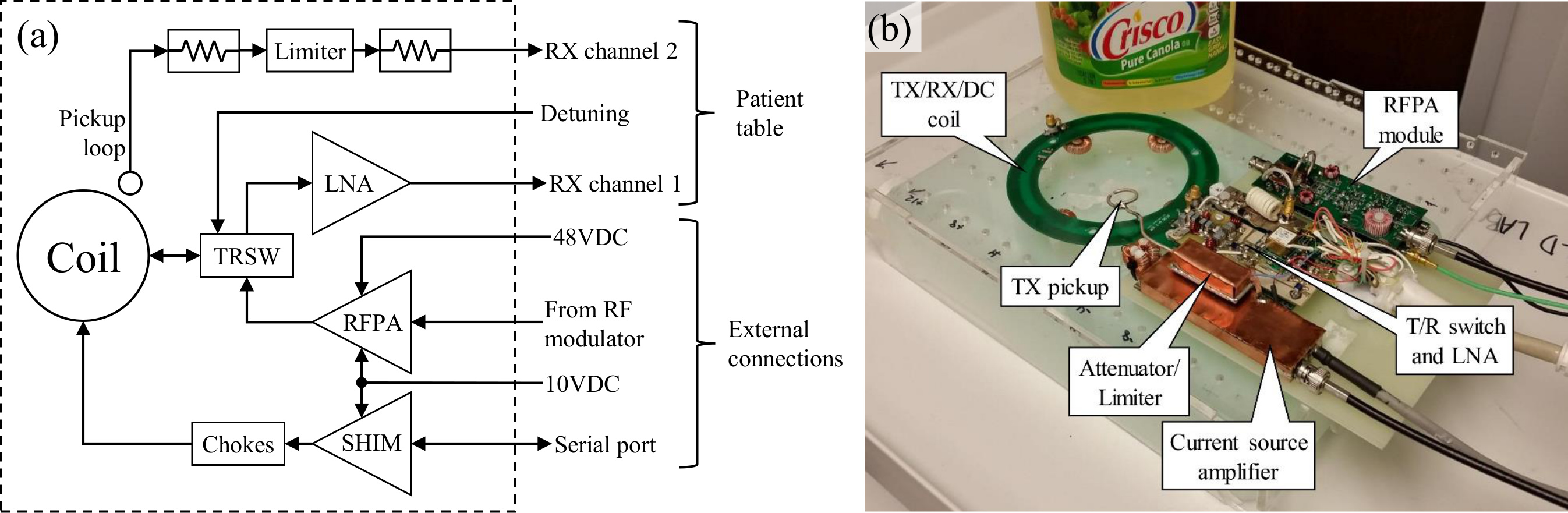
RF paths: Figure 1 shows a block diagram and photograph of the assembly. The coil is a 15cm diameter surface loop with toroidal chokes bridging all capacitors, similar to Stockmann et al4. During the receive state, the coil is coupled to the LNA (QED, Mayfield Village, OH, USA). In the transmit state, the coil is coupled to the output of a 130W high-efficiency RFPA module5. A small pickup loop placed above the coil detects the field generated by the coil during the transmit state. This allows for measurement of the true transmit pulse in order to implement iterative predistortion, or to correct MRF dictionaries. The sampled field is passed through a shielded attenuator and limiter in order to protect the scanner’s receive chain from excessive power. The LNA and pickup loop outputs are passed to the scanner’s receivers via the patient table plugs.
DC paths: The current driver is implemented as a high efficiency switchmode closed-loop current source. Four coil-splitting capacitors are bridged with toroidal chokes (L=1.89µH, ESR=50mΩ) to permit the flow of the shim currents, similar to. Two additional chokes connect the current driver to the coil. The current driver is able to step its output current with a rise/fall times of 20µs, and was capable of delivering +/-6A of continuous current without forced cooling.
Imaging Experiments: Imaging experiments were performed on a Siemens Verio 3T scanner to map the maximum B0 and B1+ produced from the RFPA and current driver. A flat saline phantom was used to heavily load the coil from below, and an oil phantom was placed above the coil. During the acquisition, the excitation pulse waveform of each TR was recorded using the pickup loop.
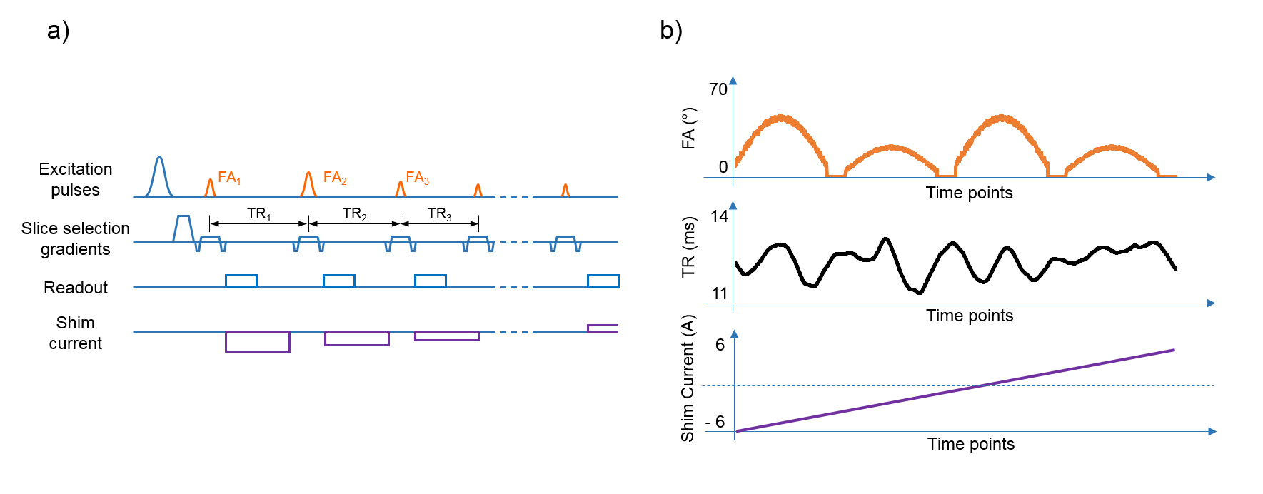
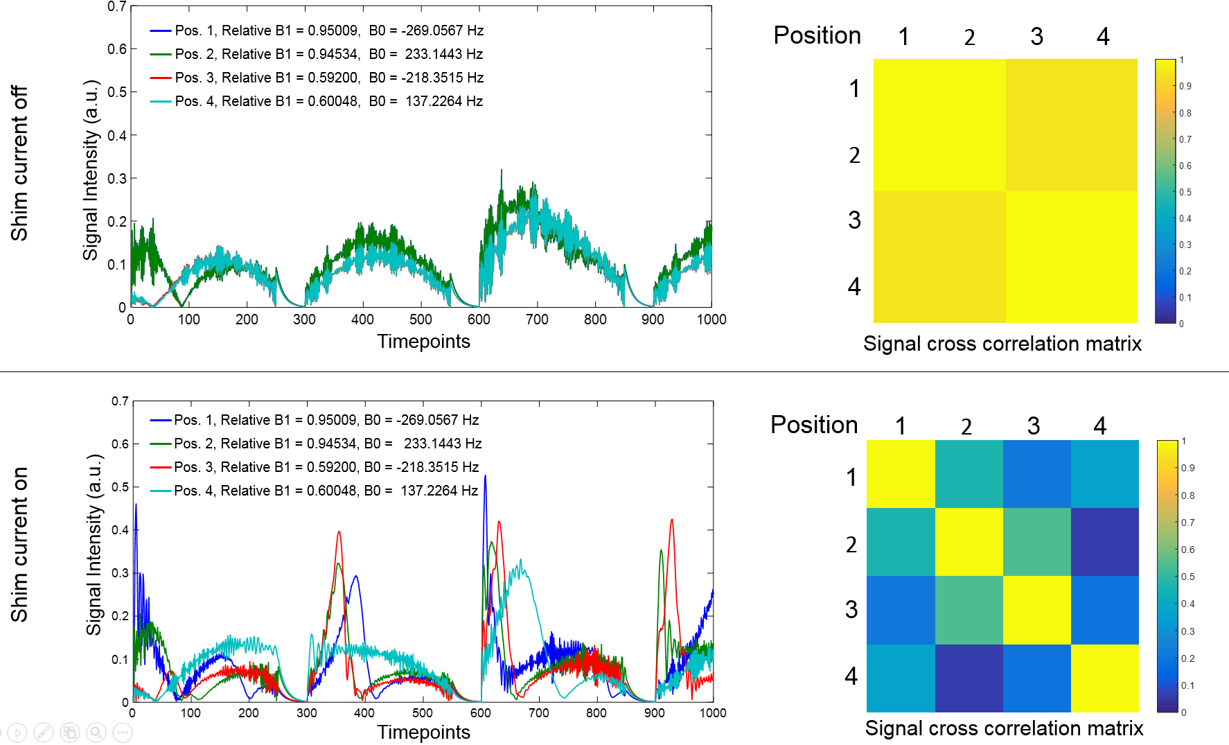
MRF simulations: Two sets of bSSFP based MRF simulations using the experimental B0 and B1+ maps were performed. In the first simulation set, signals from the same tissue type (gray matter) were simulated at four locations (see figure 2). In the second simulation set, multiple tissue types were simulated at the same location. Each simulation set was performed with the shim current fixed at 0A during the entire acquisition, and also with the shim current stepped linearly from +/-6A each TR (see Figure 3). Gaussian noise corresponding to SNR=5 was added to the simulated signals, and were then matched to tissue parameters.
Results
RF coil characterization: The loaded and unloaded Q of the coil was measured with and without the chokes and amplifiers present. The unloaded Q dropped from 360 to 236, while the loaded Q dropped from 15.9 to 15.3. Fig 3 shows the field maps from the imaging experiments.
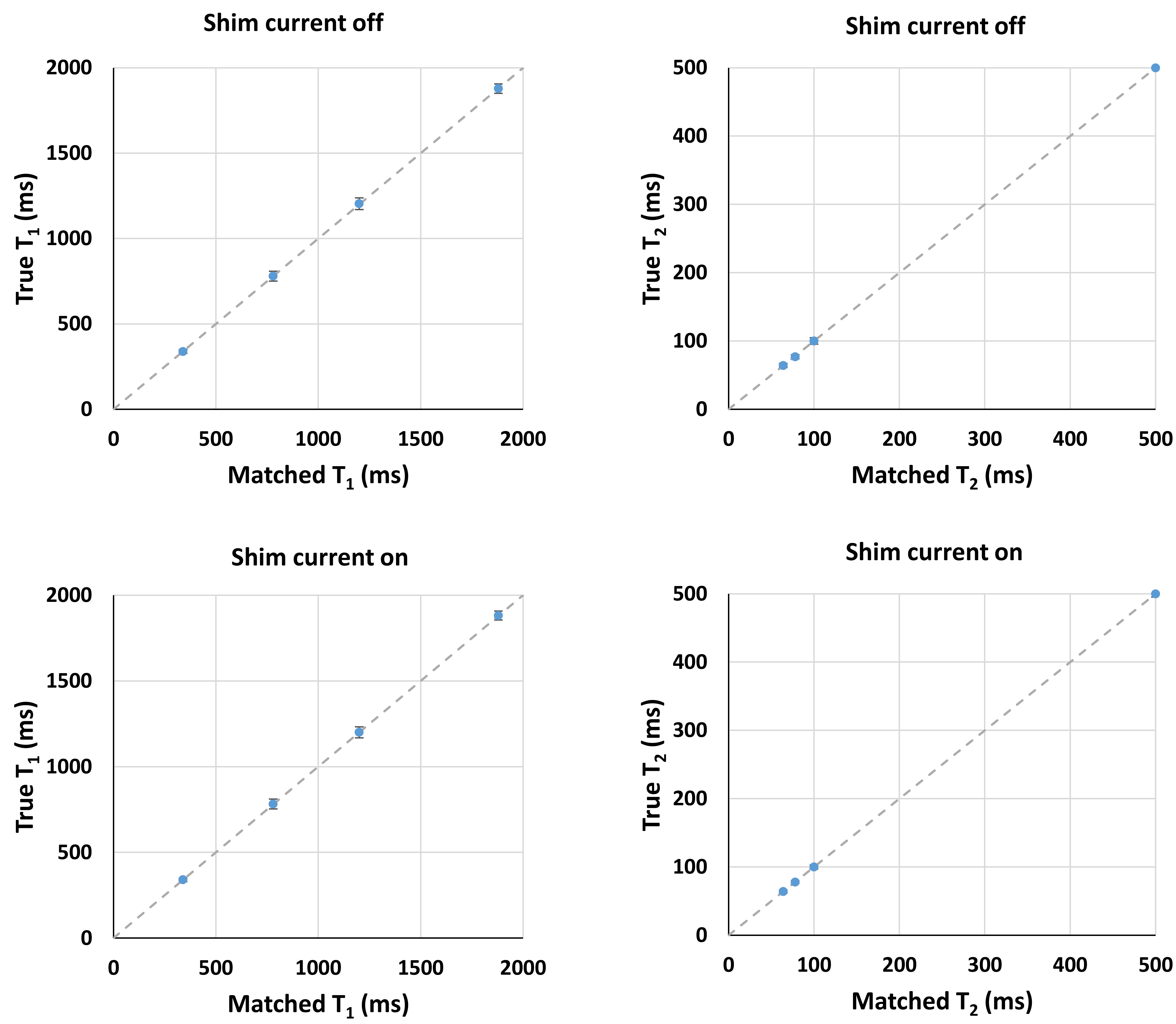
MRF simulations: We see in figure 4 that the addition of the spatio-temporally varying ΔB0 to the MRF sequence decreases the correlation between signals at different locations even though they originate from the same tissue type. Fig 5 shows results from the second set of simulations. We see that the use of the temporally varying shim does degrade matching results as compared to conventional MRF, but can allow for better separation of different pixels.
Discussion and Conclusion
Simulations based on empirical field maps showed that the addition of the spatially and temporally varying shim fields allowed differentiation of tissues at different locations while not degrading matched parameters for different tissue types at a single location. This may accelerate MRF by correcting matching errors due to aliasing. Ideally, an array of such coils would be used to further tailor the fields. In order to make this realizable, we have demonstrated a coil assembly comprising an iPRES coil and all amplifiers local to the coil. Further work will see improved integration of the three signal chains into more compact assemblies, which will then be used in an array.Acknowledgements
The authors would like to acknowledge funding from Siemens Healthcare and NIH grants NIH 1R01EB016728 and NIH 5R01EB017219.References
1. Ma, D. et al. Magnetic resonance fingerprinting. Nature 495, 187–192 (2013).
2. Han, H., Song, A. W. & Truong, T.-K. Integrated parallel reception, excitation, and shimming (iPRES). Magnetic Resonance in Medicine 70, 241–247 (2013).
3. Darnell, D., Truong, T.-K. & Song, A. W. Integrated parallel reception, excitation, and shimming (iPRES) with multiple shim loops per radio-frequency coil element for improved B 0 shimming: Higher-order iPRES B0 shimming. Magnetic Resonance in Medicine (2016). doi:10.1002/mrm.26267
4. Stockmann, J. P. et al. A 32-channel combined RF and B 0 shim array for 3T brain imaging: Combined RF and B 0 Shim Array. Magnetic Resonance in Medicine 75, 441–451 (2016).
5. Twieg, M. & Griswold, M. A. High efficiency radiofrequency power amplifier module for parallel transmit arrays at 3 Tesla. Magnetic Resonance in Medicine (2016). doi:10.1002/mrm.26510
Figures