0759
Double-Row 16-element Tight-Fit Transceiver Phased Array with High Transmit Performance for Whole Human Brain Imaging at 9.4T.Nikolai I. Avdievich1, Ioannis A. Giapitzakis1, and Anke Henning1,2
1Max Planck Institute for Biological Cybernetics, Tübingen, Germany, 2Institute of Physics, Ernst-Moritz-Arndt University, Greifswald, Germany
Synopsis
At ultra-high fields (UHF, >7T) a simple increase of the length of a single-row human head transmit (Tx) phased array cannot provide an adequate longitudinal coverage for the whole brain imaging. Multi-row (>2) arrays together with RF shimming have to be used instead. In this work, we constructed a 9.4T (400 MHz) 16-loop double-row transceiver array based on the analytical modeling. We demonstrated that simply by overlapping a very good decoupling can be obtained without additional decoupling strategies. This provides a recipe of a simple, robust, and very Tx-efficient design for parallel transmission and whole brain imaging at UHFs.
Purpose:
To optimize the transmit (Tx) performance of a human head transceiver (TxRx) phased array and provide for the longitudinal coverage suitable for the whole brain imaging at 9.4T.Introduction:
It has been previously demonstrated for ultra-high field (UHF, >7T) human brain imaging that a simple increase of the length of a single-row Tx-array cannot provide an adequate longitudinal coverage (along the magnet axis) of a whole brain (1-4). Multi-row (2 and above) arrays together with RF shimming have to be used instead (2,3,5). Also tight-fit surface loop TxRx-phased arrays (2,4) improve Tx-efficiency in comparison to Tx-only arrays (5), which are larger to fit smaller multi-channel Rx-only arrays inside. Previously, based on the analytical modeling (6) we demonstrated that at 9.4T both the magnetic and electric coupling between two heavily loaded loops can be compensated at the same time simply by overlapping, and excellent decoupling can be obtained between adjacent loops of a single-row 8-element human head tight-fit TxRx-array without additional decoupling strategies (7). In this work, we extended this idea by constructing a 9.4T tight-fit human head 16-loop double-row (2x8) TxRx-array decoupled entirely by overlapping. The developed transceiver array provides efficient transmission and the whole brain coverage at the same time.Methods:
Loop size (10.5 cm x 10 cm) was first evaluated analytically (Fig.1) and then adjusted on a bench. The array (Fig.2) measures 20 cm in width (left-right), 23 cm in height (anterior-posterior), and 17.5 cm in length. Overlapping provides very good decoupling (Fig.2D). To decrease radiation losses the array is shielded with the cylindrical shield located at 4-cm distance from the coil elements. Loaded Q-factor, QL, measured between 17 (bottom) and 30 (top), which corresponds to a QU/QL ratio between 8 and 14. We compared the performance of the tight-fit 16-channel TxRx-array with a larger 16-element Tx-only/ 30-element Rx-only (ToRo) surface loop phased array (28 cm – diameter, 19 cm - length) described previously for human head application at 9.4T (5). Electromagnetic (EM) simulations of the transmit B1+ and the local specific absorption rate (SAR) were performed using CST Studio Suite 2015 (CST, Darmstadt, Germany) and the time-domain solver based on the finite-integration technique (FIT). Three voxel models were used, i.e. a head/shoulder (HS) phantom (5), which was constructed to match tissue properties at 400 MHz (ε = 58.6, σ =0.64 S/m), and two virtual family multi-tissue models, “Duke” and “Ella”. Experimental B1+ maps were obtained using the AFI sequence (8). All data were acquired on a Siemens Magnetom 9.4T human imaging system.Results and Discussion:
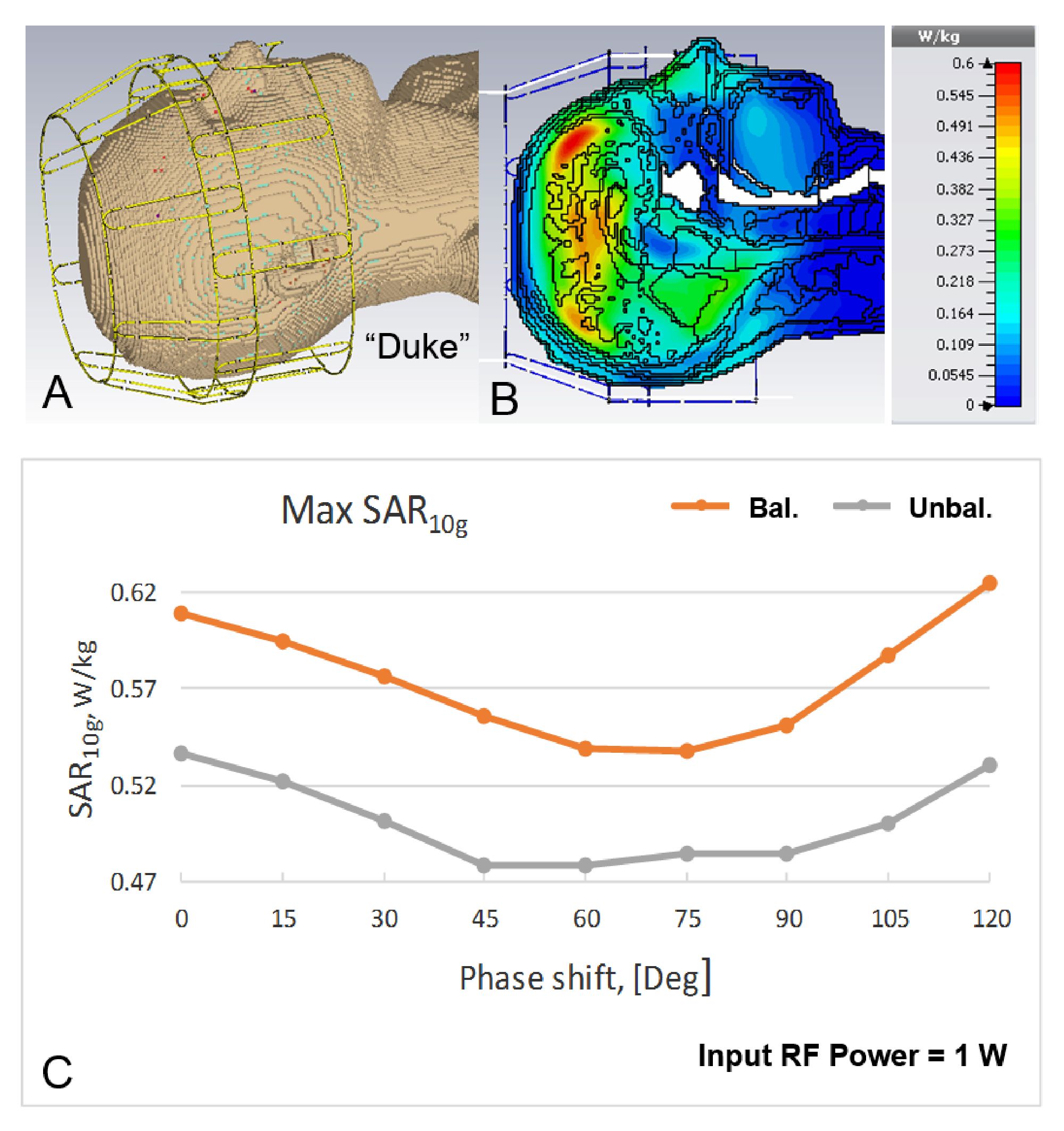
After performing safety evaluation of the array, which included EM modeling (B1+, SAR) and phantom imaging, we conducted in-vivo experiments (Fig.3). The 16-channel tight-fit TxRx-array provided ~40% improvement in B1+ efficiency (B1+/√P) compared to the larger 16-channel To- / 30-channel Ro-array, which agrees well with results obtained from EM simulations that indicate a ~2 fold increase in the RF power deposited into the tissue. Circular polarized (CP) mode (45º phase shift between adjacent loops in each row; 22.5º - between the rows) doesn’t provide a very homogeneous B1+ field at UHFs (Figs3A, 3B). However, introduction of a 70º-phase shift between the rows (Fig.3C) provides an improvement of the homogeneity (9). In-vivo images (Fig.4A) demonstrate coverage of the whole brain. Figs 4B and 4C show a comparison of the SNR maps obtained in-vivo using both arrays. While the 30-element Ro-array still has a better peripheral SNR, SNRs in the center of the head are similar. We also evaluated the dependence of the maximum local SAR10g (10g-averaged) on the phased shift, φ, introduced between the rows for the homogeneity improvement (Fig.5) (9). At φ~70º the maximum SAR10g value decreased by 13% as compared to the CP Mode. Additional drop (~30% in total) of the maximum SAR10g can be obtained by unbalanced driving of the array (Fig.5C) as suggested in (9).Conclusion:
We constructed a 9.4T (400 MHz) 16-loop (2x8) overlapped transceiver head array based on the results of the analytical modeling. We demonstrated that simply by overlapping a very good decoupling can be obtained without additional decoupling strategies. This provides a recipe for a simple, robust as well as very Tx-efficient design suitable for parallel transmission (pTx) and whole brain imaging at UHFs.Acknowledgements
No acknowledgement found.References
1) Adriany G et al, MRM 2010;63:1478. 2) Avdievich NI, Appl Magn Res 2011;41:483. 3) Gilbert KM et al, MRM 2012;67:1487. 4) Avdievich NI et al, Proc. ISMRM 22, 2014, 622. 5) Shajan G et al, MRM 71:870, 2014. 6) Avdievich NI et al, Proc. ISMRM 23, 2015, 3525. 7) Avdievich NI et al, Proc. ISMRM 24, 2016,169. 8) Yarnykh VL. MRM 2007;57:192. 9) Hoffmann J et al, MAGMA 2014;27:373.Figures
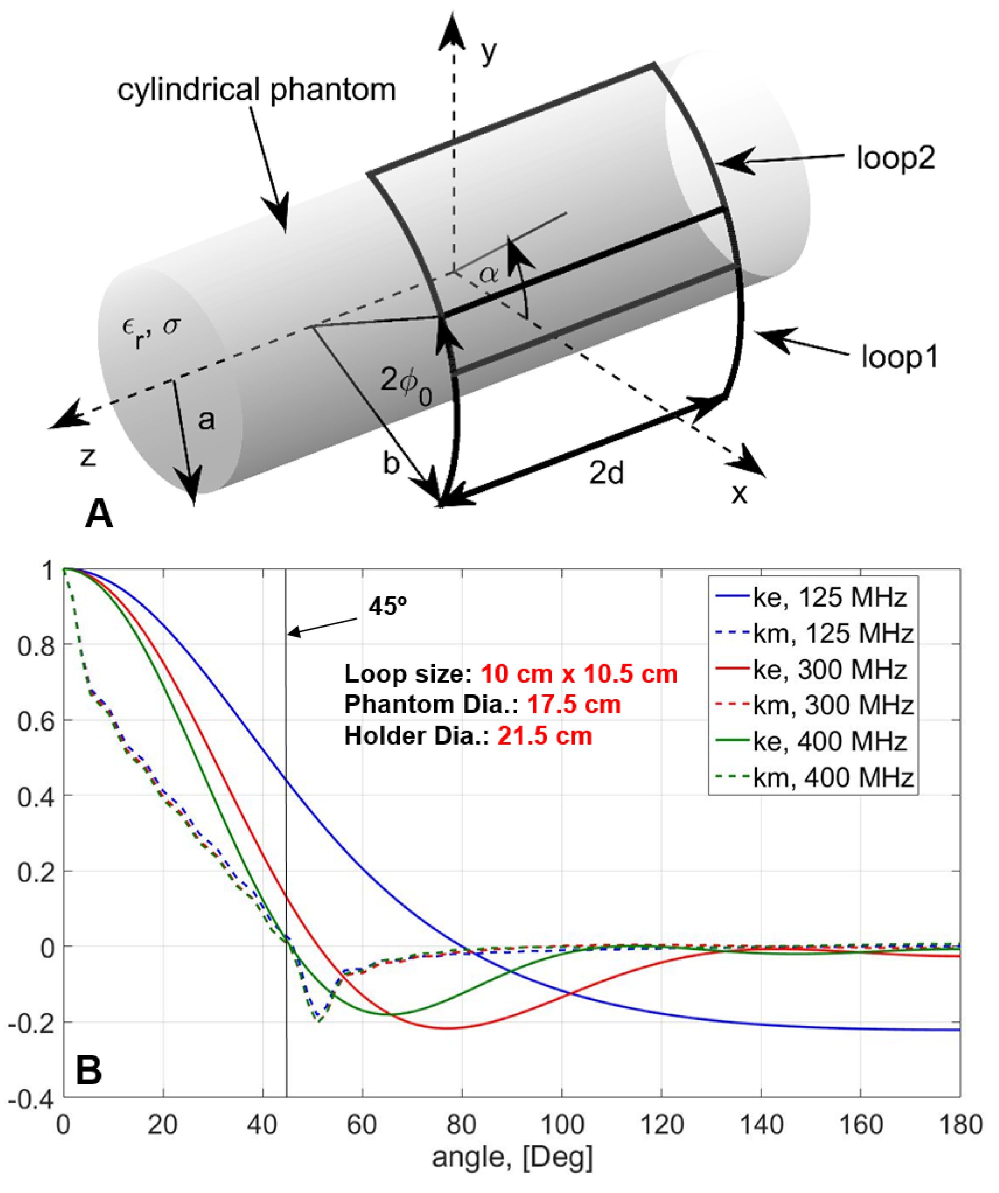
Figure
1. A) Two-loop cylindrical setup for the analytical model. B) Dependences
of the magnetic (km) and
electric (ke) coupling on
the angle between the loop centers obtained using the analytical
model.
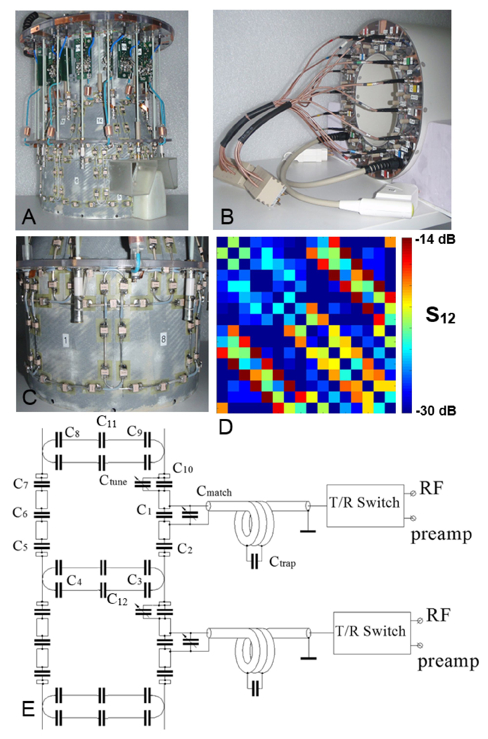
Figure
2. Photos of the tight-fit TxRx-phased array without the cover (A), and with
the cover on (B). C) Photo of two adjacent overlapped loops. D) S12
matrix obtained using the HS phantom. E) Schematics of two adjacent surface loops.
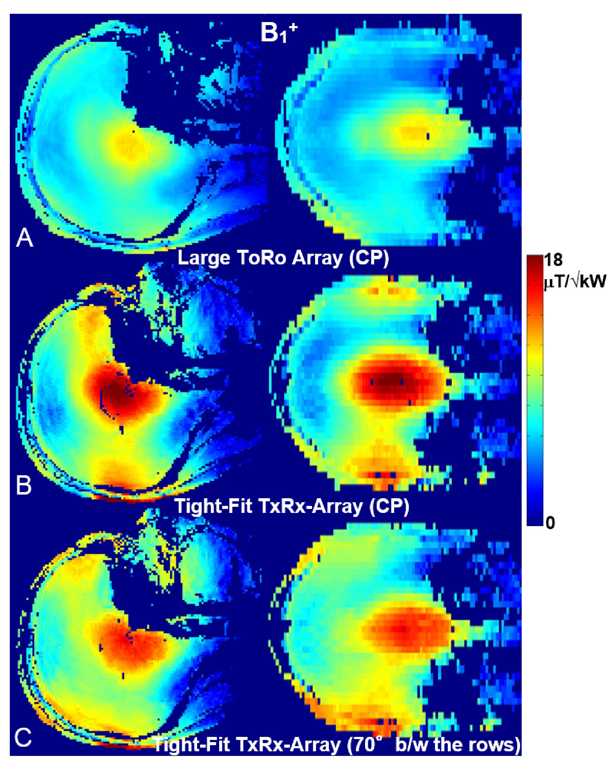
Figure
3. Central sagittal, and coronal in-vivo B1+ maps obtained using the larger ToRo-array (A) and the
tight-fit TxRx-array (B)
both used in the CP mode. D) B1+ maps
obtained using the tight-fit TxRx-array with the 70º phase shift introduced
between the rows.
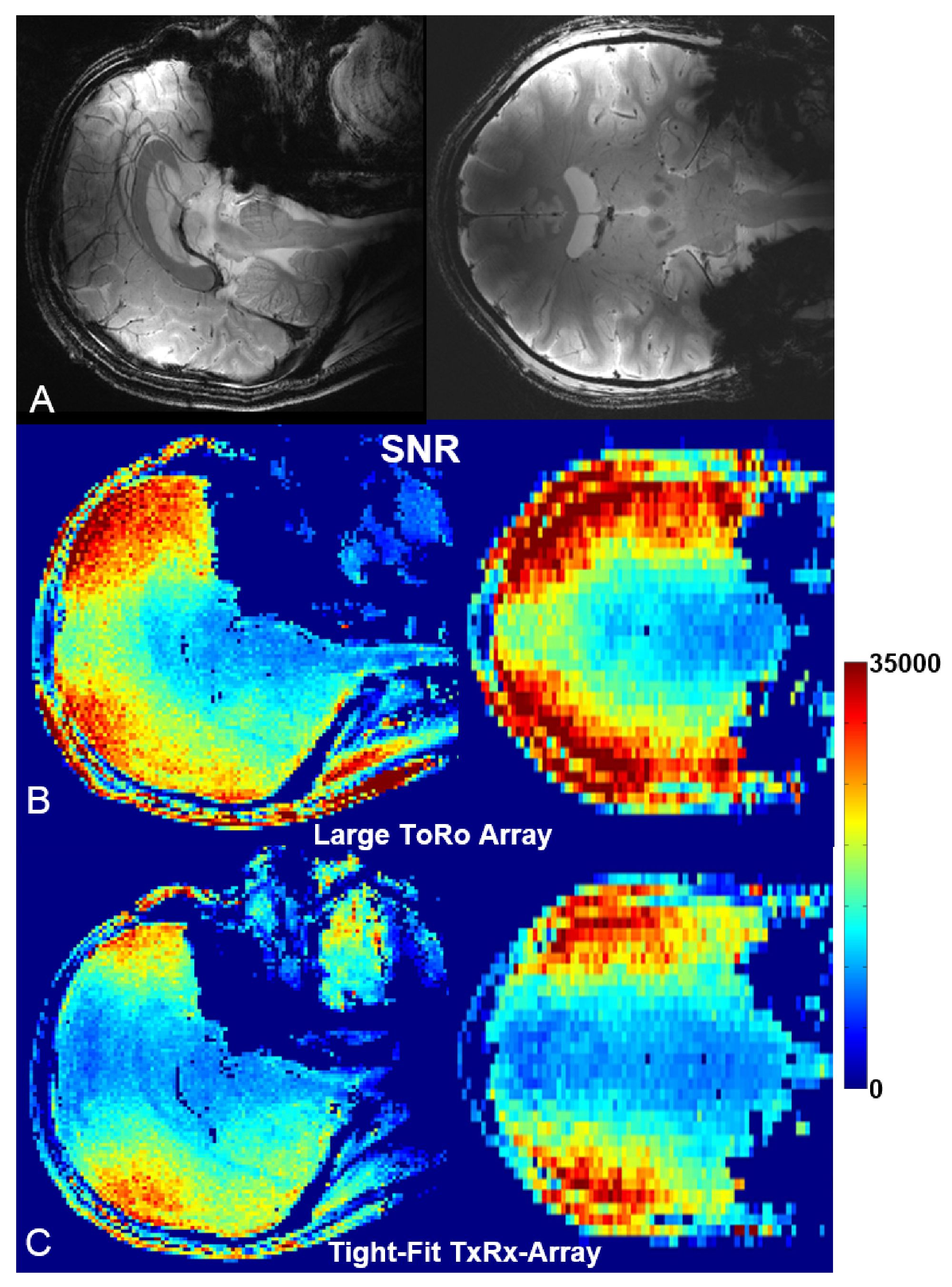
Figure
4. A)
Central sagittal, and coronal in-vivo human brain GRE images obtained with the
tight-fit TxRx-array at 9.4T. SNR maps obtained for slices
shown in Fig.3A using the larger ToRo-array (B) and the tight-fit TxRx-array
(C).
Figure
5. A) CST EM simulation model of the double-row tight-fit TxRx-phased
array loaded by the “Duke” voxel model. Lumped elements and ports are not
shown. B) Central sagittal SAR10g map (CP
Mode). C) Dependence of the maximum local SAR10g on the phase shift
between the rows obtained by EM simulations for
balanced (1:1 power distribution between the rows) and unbalanced (1:1.4
power distribution between the rows) driving.