0758
Optically Controlled Four-Channel Transceiver for 7T imaging with RF Monitoring Feedback1Advanced MRI Section, LFMI,NINDS, National Institutes of Health, Bethesda, MD, United States
Synopsis
In multi-channel RF transmission, monitoring and accurate control of amplitude and phase of the transmit signal is necessary to ensure safety. To this end, we present a four-channel transceiver array for 7T imaging built from optically-controlled on-coil amplifiers with optical real-time RF signal monitoring. Based on this monitoring signal an amplitude and phase control can be implemented for flexible, accurate and rapid control of B1 and SAR.
Introduction
Multi-channel
transmit systems are increasingly being explored for their flexibility in optimizing
B1 inhomogeneity while constraining SAR, which is particularly relevant
at high field1, 2. However,
clinical implementation of such systems has been slow due to safety concerns,
primarily those with subject-dependent SAR hotspots. These difficult to
predict hotspots result from a certain phase and amplitude combinations of the individual
transmit channels3,4.
Therefore, accurate control of amplitude and phase of the
transmit signal is necessary to ensure that the system operates in a safe
regime.This
requires monitoring of the actual amplifier output. To this end, we present a four-channel transceiver array for 7T imaging
built from optically-controlled on-coil amplifiers with optical real-time RF
signal monitoring5,6. Using this monitored feedback signal, amplitude
and phase control can be implemented for flexible, accurate and rapid control
of SAR and B1. We present preliminary data to evaluate system
performance.Methods
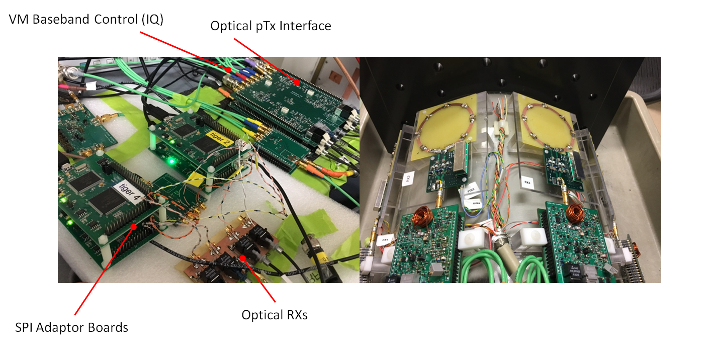
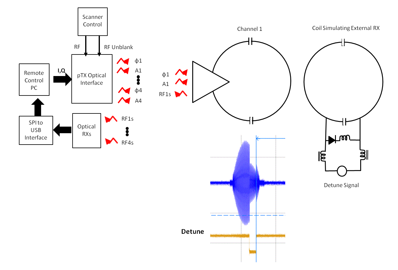
A picture of all hardware is shown in Figure 1. Our four channel on-coil transceiver prototype consisted of four 6 cm diamter loops directly connected to optically controlled amplifiers, an improved design from a previous prototype5 that can deliver 100 W peak power. By adding a custom-built TR switch and preamplifier board to each element we were able to receive signal from these same loops and send it to the scanner receiver via the standard coil interface on the patient table. The amplifiers were controlled by a custom-built pTx interface based on vector modulation that generates four optical carrier and envelope signals of which phase and amplitude are controlled from a Linux computer5. The transmit signal of each amplifier was sensed by a loop integrated in an inner layer of the amplifier PCB. It is down sampled, digitized and optically transmitted to the same computer through a dedicated SPI-to-USB interface6 for each channel. A custom user interface allowed safety monitoring, where the sensed transmit fields can be compared to the expected output. The system automatically switched off in case a deviation beyond a set threshold is detected. This same setup will allow for feedback-adjustment of amplitude and phase. An initial safety-monitoring test was performed by adding a perturbation of the transmit signal by tuning an external loop, located closed to channel 1, with a PIN diode signal (detune) in sync with the RF unblank (Figure 2). For this test, if a set threshold was exceeded the baseband control of all vector modulators (I,Q) would be automatically set for maximum RF amplitude attenuation. The new transceiver was tested in a 7T scanner (Siemens, Erlangen). Images of an oil phantom were acquired with a gradient-echo sequence, TR/TE= 250/5.44 ms, FOV= 343 x 343 mm, matrix size 128 x 128 and slice thickness 5 mm.Results
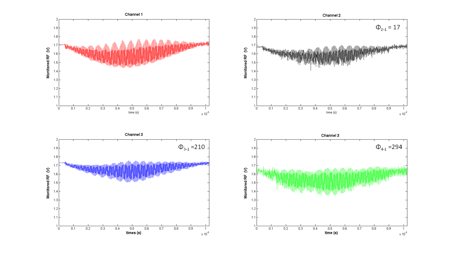
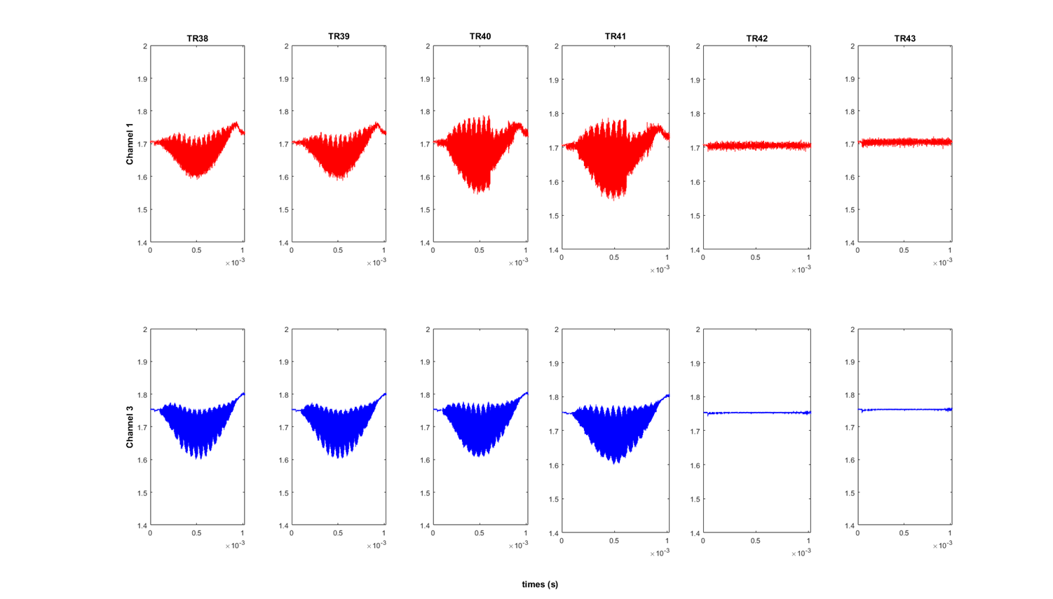
Figure 3 shows four RF feedback signals monitored at 781 kHz, and inter-channel phase difference relative to channel 1. In this case a local oscillator (LO) signal, sent (optically) for down conversion, was set to 297.0 MHz, at 200 kHz from the scanner center frequency. This could be changed in a 400 kHz range around the resonance frequency. Maximum phase and relative amplitude standard deviation were 0.00684 rad and 0.0084, respectively, for channel 4. This corresponds to a phase and amplitude SNR of 145 and 118.6, respectively, for the same channel (the other channels performed ~ 2 x better). Figure 4 shows the monitored RF pulse for channel 1 and 3 for consecutive repetition times (TR=100 ms) before and after the disturbance created by synchronous tuning of the external loop. The RF amplitude of all channels was automatically set to zero after two TR cycles (200 ms). Data collection, processing and applying updated amplitude and phase for one channel took 14.7 ms (SD=2.8 ms for 248 repetitions). The 2-TR latency results from the next transmit pulse already being queued when updated I,Q changes are applied. An image of the oil phantom was successfully acquired when transmitting with the 4-channel with phase differences for CP excitation (Figure 5).Discussion
We demonstrated a 4 channel transceiver system based on optically controlled on-coil amplifiers with RF signal monitoring and safety feedback. We will conduct further tests of the feedback under other signal conditions. This setup will help to ensure safety under the possibility of hardware failures, improve the performance of the system by correcting nonlinearities of the hardware and perform automatic calibrations in the scanner.Acknowledgements
No acknowledgement found.References
1-Mao W, Smith MB and Collings CM. Magn Reson Med. 2006 Oct;56(4):918-22.
2-Lee J, Gebhardt M, Wald LL, Adalsteinsson E. Magn Reson Med. 2012 Jun;67(6):1566-78.
3-Graesslin et al, Proc. Intl. Soc. Mag. Reson. Med 15th,2007 (Abstract 1086).
4-Graesslin I, Vernickel P, Börnert P, Nehrke K, Mens G, Harvey P, Katscher U. Magn Reson Med. 2015 Aug 74(2):589-98
5-Gudino N, Duan Q, de Zwart JA, Murphy-Boesch J, Dodd SJ, Merkle H, van Gelderen P, Duyn JH.Magn Reson Med. 2016 Jul;76(1):340-9.
6-Gudino N, de Zwart Jacco A., Duan Qi, van Gelderen Peter, and Duyn Jeff H. Proc. Intl. Soc. Mag. Reson. Med 24, 2016 (Abstract 2181)
Figures