0757
Self-Decoupled RF Coils1Institute of Imaging Science, Vanderbilt University, Nashville, TN, United States, 2Department of Radiology and Radiological Sciences, Vanderbilt University, Nashville, TN, United States, 3Department of Biomedical Engineering, Vanderbilt University, Nashville, TN, United States
Synopsis
RF arrays with large numbers of independent elements are desirable for parallel imaging and transmission. However, electromagnetic (EM) coupling between elements becomes significant as the number of coils increases and can severely impact coil performance. Several methods such as overlapping elements, L/C
Purpose
RF arrays with large numbers of independent elements are desirable for parallel imaging and transmission. However, electromagnetic (EM) coupling between elements becomes significant as the number of coils increases and can severely impact coil performance. Several methods such as overlapping elements, L/C networks and auxiliary resonators1-4 have been proposed to reduce coupling, and are effective in decoupling adjacent elements, but are usually less effective for non-adjacent elements, and are not directly applicable to recently-proposed mixed arrays such as combinations of dipoles/monopoles and loop arrays5,6. To address these problems, we propose a simple, geometry-independent self-decoupled RF coil design in which the two induced current modes in a loop coil can be adjusted to cancel each other. The method is validated in EM simulations, bench tests and MR experiments.Methods
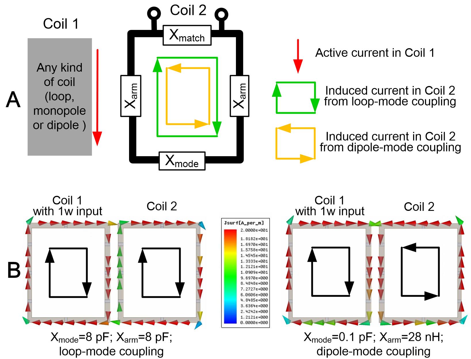
If a loop coil’s current is uneven along its conductor segments, two modes exist (loop mode and folded-dipole mode)7 (Fig. 1A). When another coil or antenna is present, current is induced in both modes due to coupling. However, if the two modes’ currents have equal amplitudes but opposite directions, the total current is zero and thus the coil is intrinsically decoupled. An impedance Xmode (illustrated in Fig. 1A) can be used to tune the current distribution and thus determine the balance between the modes. To validate this, the current distributions of two modes are simulated separately in Fig. 1B, where Xmode=Xarm=8 pF corresponds to the loop-dominating mode and Xmode=0.1 pF corresponds to dipole-dominating mode. It is found that the induced currents of the two modes have opposite directions, thus establishing the possibility to build a “self-decoupled coil”. As Xmode is varied, the coil’s resonance frequency and impedance match can be maintained by tuning Xarm and Xmatch.
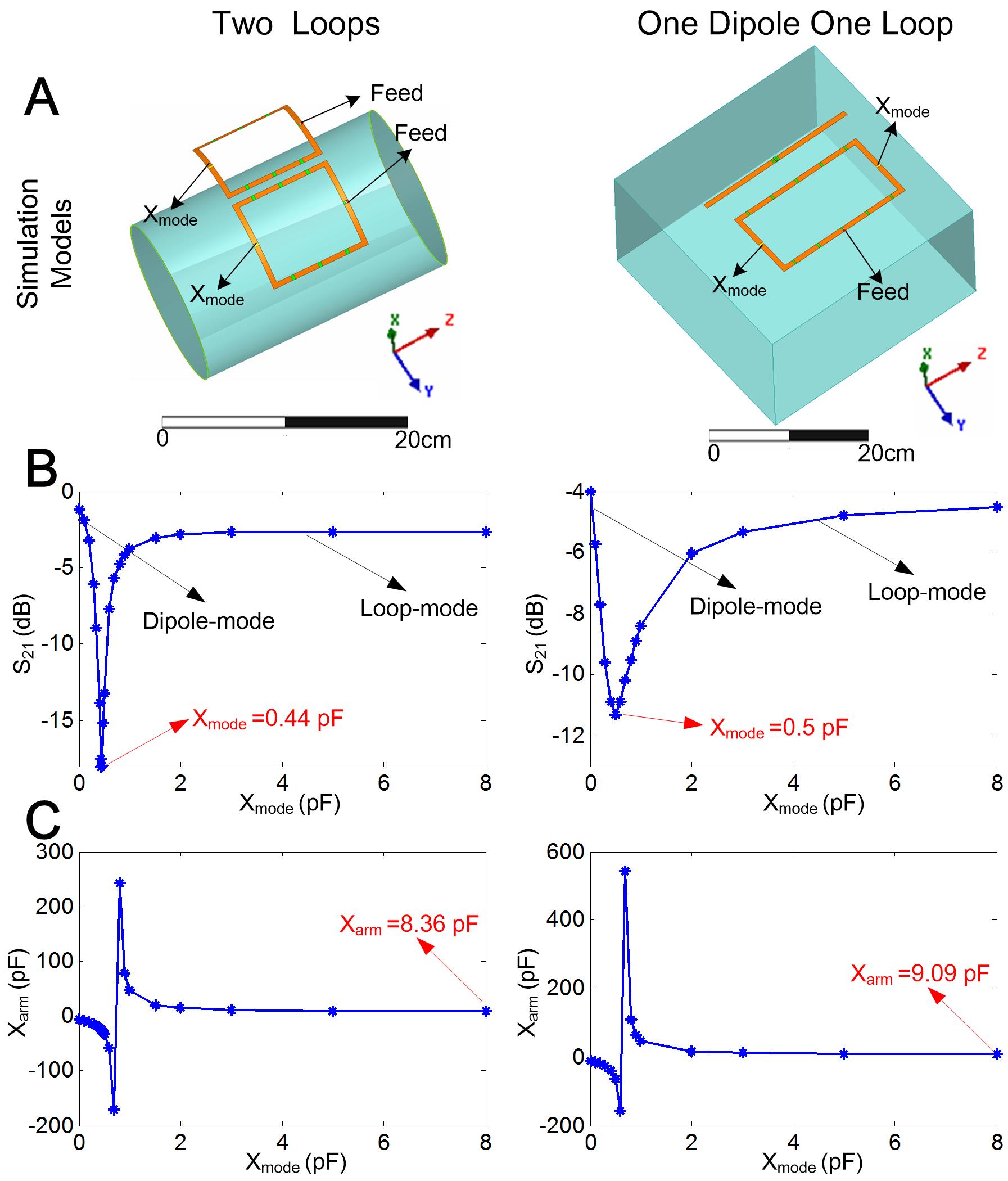
Fig. 2A shows simulation results of loop-loop and dipole-loop configurations in HFSS (Ansys, Canonsburg, PA, USA). The latter setup corresponds to a dipole and its adjacent loop, which are the most strongly coupled elements in mixed arrays5,6. For the loop-loop configurations, the loops have dimensions 10x10 cm2 and are positioned 1 cm apart. A cylindrical phantom with 15 cm diameter and 20 cm length was placed 4.5 cm below (б=0.6S/m and ξr=78) the loops. For the dipole-loop configuration, the dipole has dimensions 23x0.75 cm2 and loop has dimensions 20x9.5 cm2; the two are spaced 4 cm apart. A tank phantom with dimensions 35x30x20cm3 was placed 4.5cm below the pair (б=0.7S/m and ξr=55). All coil elements were matched to 50 Ohms and tuned to 298 MHz. Fig. 2B shows the variation in the coils’ transmission coefficients (S21) across Xmode settings. As expected, S21 is quite high when either mode dominates, but is minimized when the two modes are balanced (Xmode~0.5pF). The same arrays were then built and validated in bench measurements and MR experiments using a 7T Philips Achieva scanner (Philips Healthcare, Cleveland, Ohio, USA).
Results
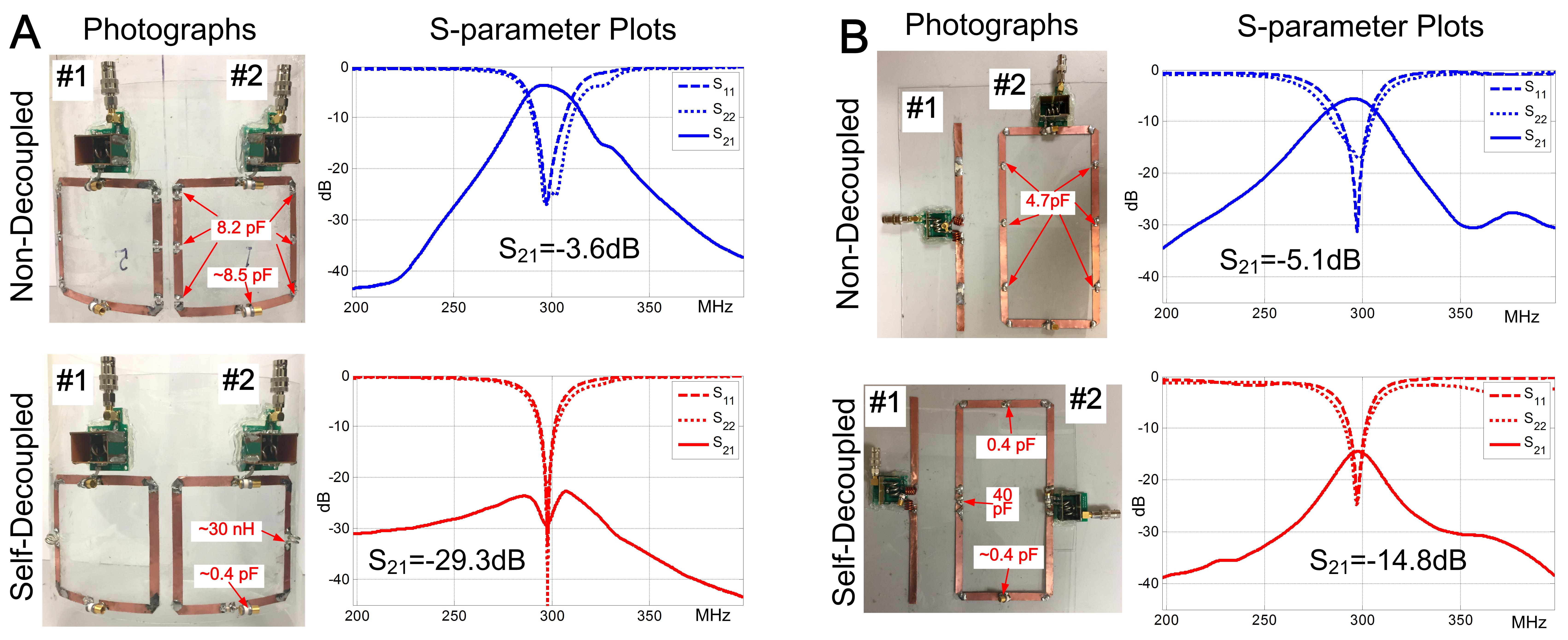
Fig. 3A and 3B show the constructed non-decoupled and self-decoupled coils with loop-loop and dipole-loop configurations, respectively. The non-decoupled loop is a conventional design where Xmode approximately equals Xarm. In the self-decoupled coil, Xmode is about 0.4pF which is also consistent with the simulation results in Fig. 2. Using self-decoupled coils, the isolation was improved from -3.6dB to -29.3dB for the loop-loop configuration (Fig. 3A), and was improved from -5.1dB to -14.8dB for the dipole-loop configuration (Fig. 3B).
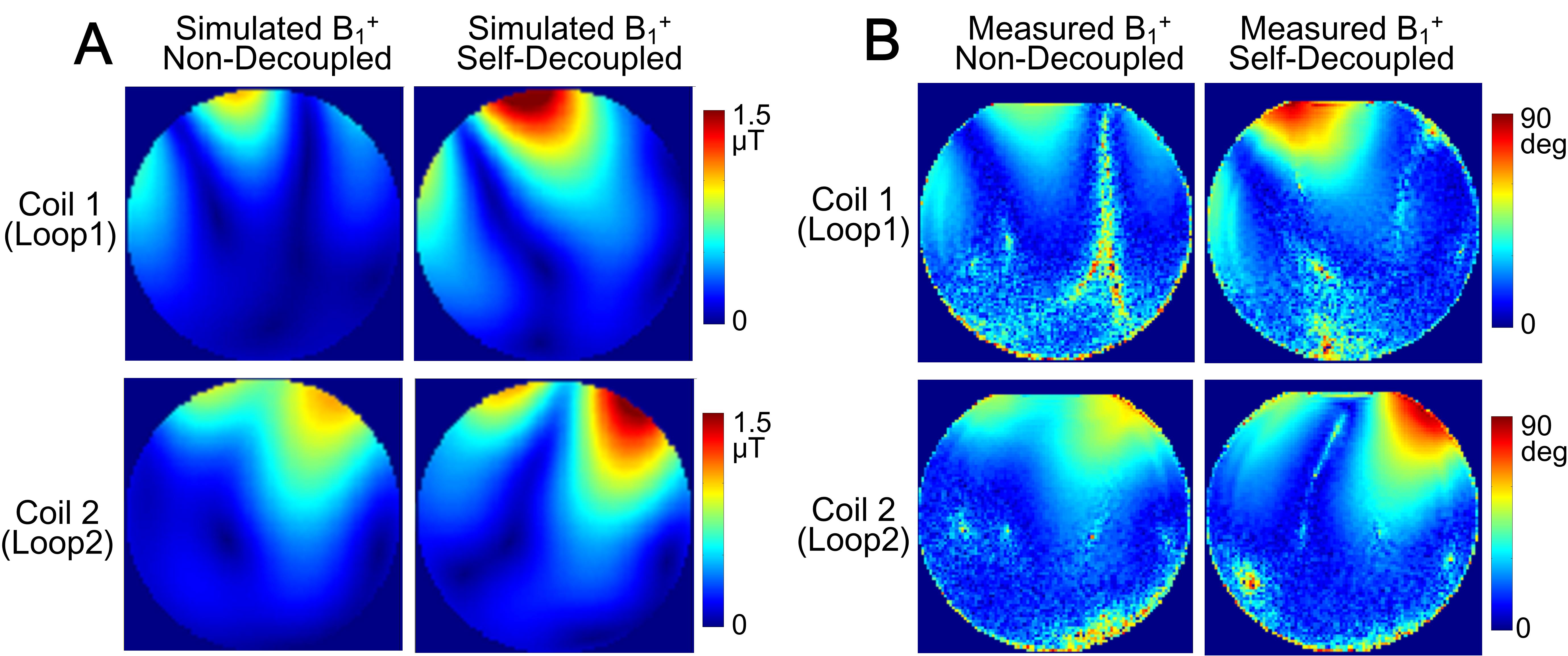
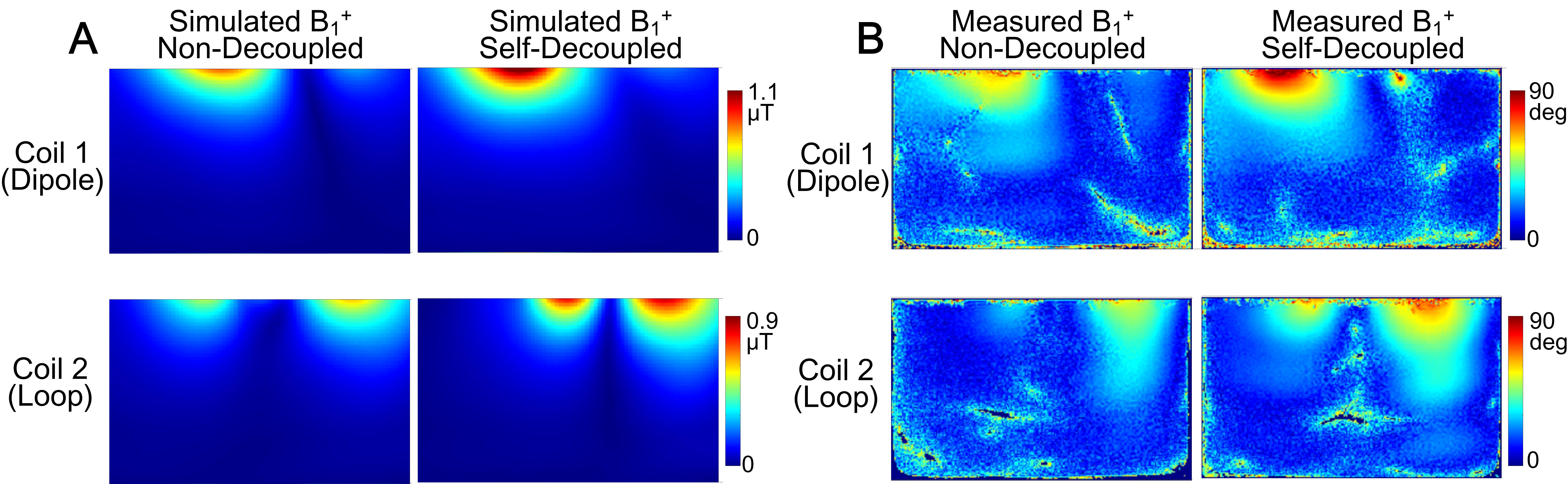
During transmission, the coupled RF power will be absorbed in circulators/terminators and wasted. Therefore self-decoupled coils with excellent isolation are expected to exhibit higher transmit efficiency compared to non-decoupled coils. For the loop-loop configuration, Loop 1 (left) and Loop 2 (right) using the self-decoupled design have an efficiency increase of ~70% and ~47%, respectively (Fig. 4). Fig. 4 also shows that individual B1+ patterns are severely distorted in non-decoupled coils. For the dipole-loop configuration, the dipole and loop using the self-decoupled design have an efficiency increase of ~39% and ~24%, respectively (Fig. 5).
Discussions and Conclusion
We proposed and validated a self-decoupled loop coil concept, which enables excellent isolation between a loop and other elements in closely-placed arrays (-30dB) with no other decoupling treatments. Self-decoupled RF coils have simple structures and can be used for mixed arrays as well as loop-only arrays. The self-decoupled coils exhibited the same B1 pattern as a conventional loop (Fig. 4) even though they had uneven currents on the end conductor segments. This is because B1=(Bx±By)/2 is mainly produced by the current on the vertical conductor segments arms. This method could be used at lower and higher magnetic fields (3T or 9.4T) so long as the coil dimensions are not extremely small (>1/15λ).Acknowledgements
This work was supported by NIH R01 EB 016695 and NIH R21 EB 018521.References
1. Roemer PB, Edelstein WA, Hayes CE, Souza SP, Mueller OM. 1990. The NMR phased array. Magn Reson Med 16:192–225.
2. Wang J. 1996. A novel method to reduce the signal coupling of surface coils for MRI. Fourth Annual Meeting of ISMRM. p 1434.
3. Wu B, Zhang X, Qu P, Shen GX. Design of an inductively decoupled microstrip array at 9.4 T. J Magn Reson 2006; 182: 126–132.
4. Li Y, Xie Z, Pang Y, Vigneron D, Zhang X. ICE decoupling technique for RF coil array designs. Medical Physics. 2011;38(7):4086-4093. doi:10.1118/1.3598112.
5. Chen G, Lakshmanan K, Sodickson D, Wiggins G. A combined electric dipole and loop head coil for 7T head imaging. In Proceedings of the International Society of Magnetic Resonance in Medicine 23rd Annual Meeting, Toronto, ON, Canada, 2015. p 3133.
6. Yan X, Wei L, Xue R, Zhang X. Hybrid monopole/loop coil array for human head MR imaging at 7T. Appl Magn Reson. 2015;46 (5):541-550. doi:10.1007/s00723-015-0656-5.
7. Lakshmanan K, Cloos M, Lattanzi R, Sodickson D, Wiggins G. The Loopole Antenna: Capturing Magnetic and Electric Dipole Fields with a Single Structure to Improve Transmit and Receive Performance. In Proceedings of the International Society of Magnetic Resonance in Medicine 23rd Annual Meeting, Milan, Italy, 2014. p 0397.
8. Nehrke, K. and Börnert P. 2012. DREAM—a novel approach for robust, ultrafast, multislice B1 mapping. Magn Reson Med, 68: 1517–1526. doi: 10.1002/mrm.24158
Figures