0745
Flexible and compact hybrid metasurfaces for enhanced ultra high field in vivo magnetic resonance imagingRita Schmidt1, Alexey Slobozhanyuk2,3, Pavel Belov2, and Andrew Webb1
1Radiology, Leiden University Medical Center, Leiden, Netherlands, 2Nanophotonics and Metamaterials, ITMO University, St. Petersburg, Russian Federation, 3Nonlinear Physics Center, Australian National University, ACT 2601, Australia
Synopsis
In previous research it has been shown that high permittivity material pads can be used for global and local RF shimming, as well as local SNR increase. Another recent approach is using metamaterials. In this study we designed a thin, compact and flexible metasurface which consists of metallic strips attached to 8mm thick pad made from a CaTiO3 suspension in water. We show applications of the hybrid metasurface in an examination of the human brain at 7T, concentrating to produce a local increase in the SNR in the occipital cortex for imaging as well as for spectroscopy.
Introduction
In previous research it has been shown that high permittivity material pads can be used for global and local RF shimming, as well as local SNR increase1-4. Another approach for increasing local sensitivity and efficiency of the pulses is using metamaterials. Several studies have shown proof-of-principle implementations of metamaterials 5-8. However, the vast majority of these implementations are based on three-dimensional metamaterial structures that have very large physical dimensions. This is particularly problematic when incorporated in a full setup that includes a large array of RF receive coils placed in the vicinity of the body. In this study we designed a thin, compact and flexible metasurface which consists of metallic strips attached to 8 mm thick pad made from a CaTiO3 suspension in water. Specifically, we show applications of the hybrid metasurface in an examination of the human brain at 7 Tesla, concentrating on using the metasurface to produce a local increase in the SNR in the occipital cortex for imaging as well as for spectroscopy.Methods
Figure 1 shows the structural geometry of the metasurface with a full structure size of 17.5x17.5x0.9 cm3 including a 0.8 cm thick dielectric layer and a plastic container on which copper strips were attached. The high permittivity dielectric layer consists of a CaTiO3 suspension in water (volume ratio of 3:1 v/v) with a relative permittivity of 110 and conductivity of 0.09 S/m, which allowed a flexible structure to be formed. 3D EM simulations of the B1+ field were performed using FIT (finite integration technique) software (CST Microwave Studio, Darmstadt, Germany). All B1+ maps were normalized to an accepted power of 1 Watt. The simulation setup included a 16-rung high pass quadrature birdcage coil (inner diameter 30 cm; rung length 18 cm), corresponding to the transmit coil used for experimental measurements. The coil was loaded with the Virtual family model ”Ella” 9 with the mesh resolution of 1.0 x 1.0 x 1.0 mm3. The phantom setup simulations used a rectangular shape oil phantom with either a flat metasurface structure or a simple high permittivity pad placed on top. In the in vivo simulations, the metasurface structure was curved to best fit the shape of the head. A quadrature birdcage coil (Nova Medical NM-008A-7P) was used for RF transmission, and a close-fitting 32-channel array coil (Nova Medical NMSC-025-32-7P) for signal detection. Phantom and in-vivo images of a volunteer were acquired on a Philips Achieva 7 T MRI system. The images included a standard gradient-echo sequence that was used for SNR estimation and B1+ maps images were acquired using the DREAM 10 sequence. The localized 1H spectroscopy used STEAM sequence with TE of 12 ms, mixing time of 13 ms and TR of 3000 ms, 15x15x15 mm3 voxel, 64 averages.Results
Figure 2 demonstrates phantom results with an increase of the B1+ in the simulation of approximately a factor-of-three close to the metasurface and similar experimental results. Figure 3 shows simulations of a full setup including human brain comparing setups with dielectric pad only, with copper strips only and with the metasurface structure. Figure 4 shows experimental results of the enhanced B1+ produced by the metasurface in the occipital cortex, as well as the higher signal intensity on a standard gradient echo image. Four volunteers were scanned and the average enhancement ratio for the RF transmit field was 2.0±0.3 and for the receive field 1.9±0.2. Taking into account the increase in maximum SAR, the increase in transmit efficiency per square root of maximum SAR was a factor of 1.6. An example of a localized 1H spectrum is demonstrated in Figure 4c with an increase of 50% in the SNR, which agrees well with the increase in the simulated B1- field integrated over the spectroscopic volume.Conclusions
This study has demonstrated a new design of a flexible and compact metasurface structure which can enhance the local RF transmit and receive efficiency. Since the design is thin and flexible it can be shaped to the anatomy of the patient, which is essential for combined operation with high density MRI receive arrays. The structures enable manipulation of the magnetic field distribution in the region of interest, demonstrating the first applications of metasurfaces for in-vivo imaging and spectroscopy of the brain, concentrating on the occipital cortex as a region of interest. We have shown results at very high field, but this approach can also be used at lower fields which are currently used for most clinical studies.Acknowledgements
We are grateful to I. Ronen for help with in-vivo spectroscopy experiment. This work was supported by an ERC Advanced Grant and NWO Topsubside (AGW). The work of A.S. and P.B. has been partially supported by Russian Science Foundation (Grant 15-19-20054). .References
[1] Haines K. et al. J.Magn.Reson. 2010; 203: 323-327. [2] Yang Q.X. et al., Magn Reson Med. 2011; 65:358–362. [3] Teeuwisse W.M. et al., Magn Reson Med. 2012; 67:912-918. [4] Brink W.M. et al. Magn.Reson.Med. 2014; 71: 1632-1640. [5] Freire, M. J., et al. J. Magn. Reson. 2010; 203: 81–90. [6] Wiltshire, M. C. K. et al. Science. 2001; 291: 849–851. [7] Radu , X. , et al. Metamaterials, 2009; 3(2): 90-99. [8] Slobozhanyuk, A. P., et al. Adv. Mater. 2016; doi: 10.1002/adma.201504270, [8] Zivkovic, I. , Scheffler, K. Proc. Intl. Soc. Mag. Reson. Med., 2014; 22, 4834. [9] Christ, A., et al. Phys. Med. Biol.,2010; 55: N23–38. [10] K. Nehrke K., Börnert P., Magn. Reson. Med. 2012; 68: 1517–1526.Figures
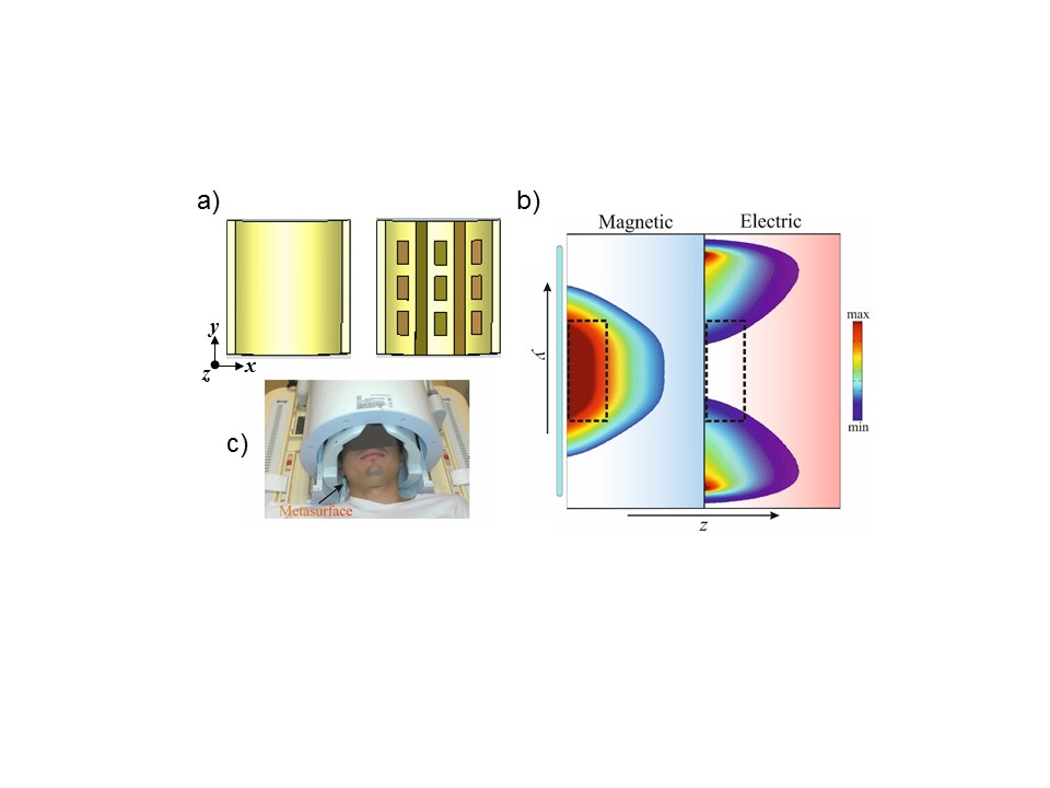
Figure 1: a) Schematic setup of the hybrid
metasurface, including high permittivity
dielectric substrate (left) combined with its metallic structure (right). b)
Numerically calculated magnetic (left) and electric (right) field maps in
vacuum near the metasurfaces (shown as a blue rectangle). The region of
interest is depicted as black dashed rectangle. c) A photograph of the in-vivo
experiment including the transmit and receive coils and the metasurface. The structure
included : 25 micrometre thick copper strips, long strips of 17.5 cm and a 3x3 matrix of short strips (3 cm
length). The distance between the strips was 1 cm.
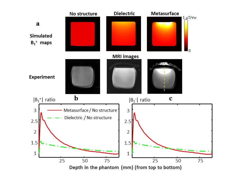
Figure 2: Experiments
to simulate and measure the transmit (B1+) and receive (B1-)
fields in an oil phantom. a, B1+ maps and the
experimentally acquired MRI low flip angle images: (left to right) no
artificial structure, with dielectric pad only and with the metasurface
structure. b, Measured B1+
profile (along the yellow dashed line).
c, Measured B1- profile
(along the yellow dashed line). The metasurface is placed on top of the
phantom.
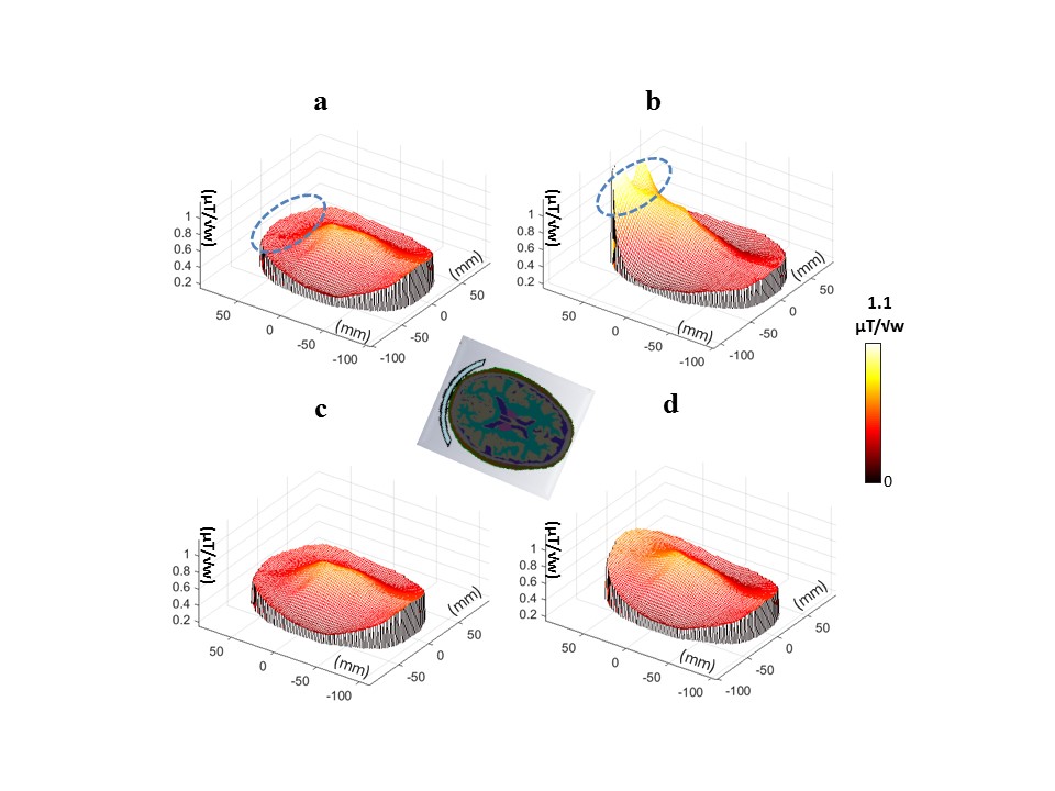
Figure 3: EM simulations of the full human model. a-d, Mesh plots of the
B1+ distribution along a central axial cross-section of
the brain for the following setups: (a) no
structure, (b) with metasurface tuned at 7 T, (c) with metallic strips only,
and (d) with the dielectric substrate only.
The axial cross section of the brain and the metasurface location (in
blue) is shown in the centre. The blue
dashed ellipse shows the region of interest in the occipital cortex.
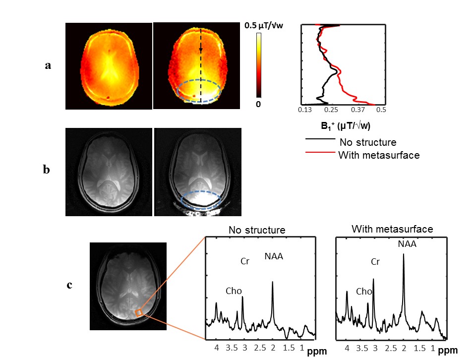
Figure 4: In-vivo imaging and spectroscopy results with and without the
metasurface. (a) B1+ maps
and profile along the dashed black line. (b)
Low flip angle MR images of the brain. (c) Localized 1H
spectroscopy without (left) and with (right) metasurface (the voxel is shown by
the orange overlay in the anatomic image). The
gradient echo sequence parameters: FOV 24x24 cm2, resolution 1.5 x 1.5 x 5.0 mm3, TR/TE 10/3.4 ms, flip-angle 5 °; and for
DREAM sequence: FOV 24x24 cm2,
resolution 2.5 x 2.5 x 5.0 mm3, TR/TE 3/1.7 ms, B1+
encoding tip-angle 50° and imaging tip-angle 10°.