0741
Operator Controlled Illumination of Active Catheter Tips using a Variable Attenuator1Deptartment of Radiology, Medical Physics, Medical Center – University of Freiburg, Freiburg, Germany, 2Department of Cardiology and Angiology, University Heart Center, Freiburg, Germany
Synopsis
Accurate visualization of catheter tip is important in MR-guided interventional procedures, in particular in the coronary arteries where the tip orientation is essential to introduce the catheter into the target vessel. Active catheters generally provide a positive MR signal around the tracking coil at the tip. In this study, an operator-controlled variable attenuator is attached to an active catheter to enable rapid manual adjustment of the tip signal by the operator. The system was tested in an animal experiment at 3 T, and the active catheter was successfully introduced into the left coronary artery multiple times.
Introduction
MRI-guided coronary artery catheterization has been shown to be feasible by simultaneous active visualization of the guiding catheter and the guidewire [1], [2]. Accurate visualization of catheter tip is crucial to provide real-time position information and the tip orientation. Active catheters generally provide an illuminated region around the tip [3], [4], but the orientation of the tip is often missing, and tip deformation causes changes in loading and inductance resulting in variable tip signals.
In this work an active coronary artery catheter was constructed and combined with an operator-controlled brightness adjustment unit to be able to adjust the tip signal in real time. Performance of the active catheter and the control circuit was evaluated on the test bench, in a phantom model and with electromagnetic simulations. The system was finally tested in a pig model at 3T during left coronary artery intervention.
Methods
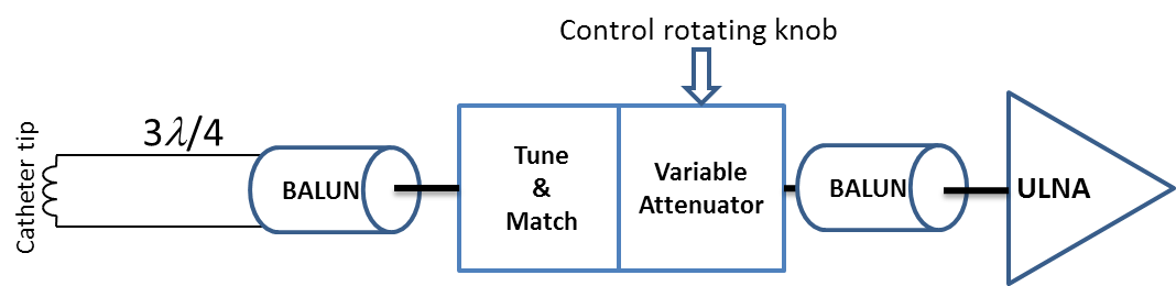
An active catheter was constructed from a commercial 5F Tiger tip-shaped guiding catheter (Optitorque, Terumo Medical Corporation, Belgium) with a loop coil at the tip (1.6mmx18mm) using 0.1mm-diameter enameled copper wire. A 400mm-diameter coaxial cable was connected to the loop, and after a 3λ/4 cable length the coaxial cable was connected to the tune/match box via bazooka and solenoid BALUNs placed consecutively. The output was then connected to a receive channel of a 3 T MR system (Magnetom PRISMA, Siemens, Erlangen). An overview of the system is shown in Fig.1.
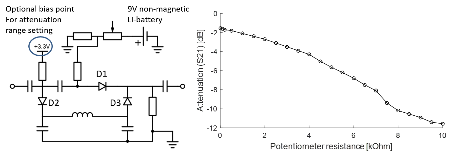
A PIN diode based attenuator circuit was designed for a matched attenuation with minimal reflection at high attenuation state (S11 = -6.7 dB, S22 = -7.2 dB). As shown in Fig.2, a π network was formed by three PIN diodes (MA4P7446F-1091, M/A-COM Technology Solutions, Inc., Lowell, USA), in which the PIN diodes behave as voltage-controlled resistors. As the voltage drop on D1 increases, the resistance in the RF path will be reduced, thus the attenuation of the signal at the coil output will be decreased. An inductor together with two shunt capacitors are included to prevent signal leakage from D2 to D3 that would impair the performance of the circuit. A non-magnetic 9V-battery was integrated as the voltage source together with a 10 kΩ potentiometer with rotating knob and a push-button switch. The battery provides a maximal current of 8mA corresponding to a life-time of 150 hours in maximal usage.
Using a real time sequence (trueFISP: TR=223 ms; TE=1.5 ms; FoV 280x280 mm2; base resolution: 176x176; flip angle: 20°), the circuit was tested in a tap-water phantom and a swine study. In the animal experiment, higher resolution ECG triggered images were also acquired (TR=673 ms; TE=1.6 ms; FoV 280x280 mm2; base resolution: 192x192; flip angle: 42°).
Results and Discussion
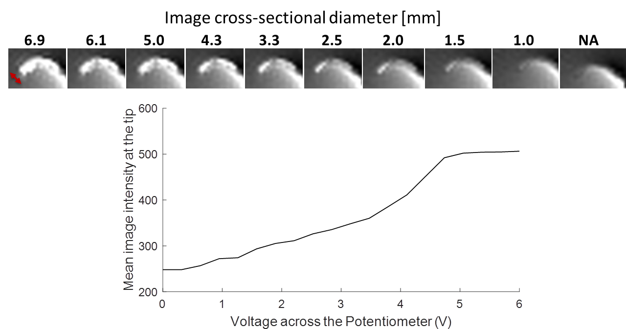
In Fig.2, potentiometer resistance and the attenuation behavior is shown. The circuit covers an attenuation range from -1.5 dB to 11.5 dB. In phantom measurements, the potentiometer was rotated slowly and the images corresponding to different attenuation states are shown in Fig.3. Optimal attenuation settings for a good visualization of the tip profile were found in real-time. Image intensity of a manually selected region of interest (ROI) at the tip and corresponding voltage level is shown in Fig.3.
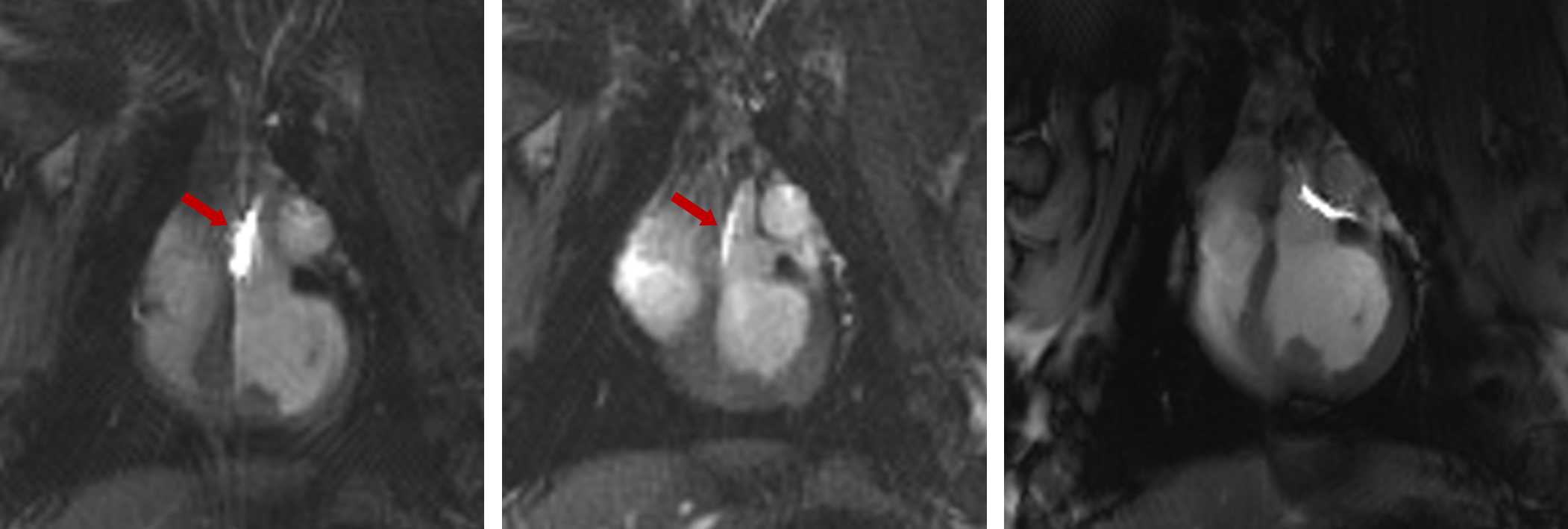
Figure 4 shows three images from the coronary artery intervention in a pig. Without brightness adjustment, the loop coil intensity is too high masking anatomical detail, and after adjustment it could be clearly visualized by the operator, and even switched off for improved visualization of the anatomical details at the coronary artery.
Variable attenuator enables instant control of the catheter signal without interrupting the image acquisition. Even though most MRI systems can control the individual signal levels from coils by software, the proposed hardware is advantageous as it is a system-independent solution which can be integrated into any MR-system, and it provides a direct interface for the interventionalist at the magnet. The intensity adjustment can also be used to find catheters that are near the imaging slice by increasing the signal from the tip.
Acknowledgements
Financial support from DFG grant BO3025/2-2 is gratefully acknowledged.
We are thankful to Roland Galmbacher for his help during the animal experiments.
Finally we thank Eugen Hoffman from Biotronik AG for his support and for providing the raw material of the catheters.
References
[1] J. M. Serfaty, X. Yang, T. K. Foo, A. Kumar, A. Derbyshire, and E. Atalar, “MRI-guided coronary catheterization and PTCA: A feasibility study on a dog model,” Magn. Reson. Med., vol. 49, no. 2, pp. 258–263, 2003.
[2] R. A. Omary, J. D. Green, B. E. Schirf, Y. Li, J. P. Finn, and D. Li, “Real-time magnetic resonance imaging-guided coronary catheterization in swine.,” Circulation, vol. 107, no. 21, pp. 2656–9, Jun. 2003.
[3] M. Bock, S. Volz, S. Zühlsdorff, R. Umathum, C. Fink, P. Hallscheidt, and W. Semmler, “MR-guided intravascular procedures: real-time parameter control and automated slice positioning with active tracking coils.,” J. Magn. Reson. Imaging, vol. 19, no. 5, pp. 580–9, May 2004.
[4] M. Bock and F. K. Wacker, “MR-guided intravascular interventions: Techniques and applications,” J. Magn. Reson. Imaging, vol. 27, no. 2, pp. 326–338, Feb. 2008.
Figures