0739
A Method for a Wireless Marker Using a Monopole Antenna for Endovascular Catheter Navigation1Radiology and Biomedical Imaging, University of California San Francisco, San Francisco, CA, United States
Synopsis
Inductively coupled RF coils have been used as markers for MR guidance of endovascular catheters using lumped elements, and a monopole antenna could be used as a marker that is more compact and easy to build. We built three prototypes for 3T, acquired GRE sequences and B1+ maps in two orientations, and modeled electromagnetic fields using low and high permittivity dielectric coating on the monopole. Measured Q-factors were 7.6–11.7, scaled experimental B1+ of marker signal were 198–272%, and modeled electric fields were reduced. This work demonstrates feasibility of a monopole antenna as a wireless marker for interventional MRI.
Introduction
Wireless resonant circuits (wRCs), or inductively coupled RF coils, have previously been used as markers for MR guidance of endovascular catheters using lumped elements with a variety of inductor geometries (1–5). Depending on the coil geometry, the signal amplification changes with orientation, and lumped elements both increase the size and decrease the flexibility of the catheter, making them less practical for neurointerventional use. The monopole antenna has previously been used for imaging and has the advantage of a compact and practical structure (6,7). The monopole antenna could be used as a marker, and could be more compact and has a more practical structure since it does not need lumped elements to support the resonance, while also providing good signal. New flexible high dielectric materials (HDM) have been developed for MR imaging coils (8), which could be applied to a monopole antenna marker to reduce its electric fields. Simulations of resonant markers in B1 fields have previously been performed to predict and optimize the design and performance of wRCs (1,9,10). The purpose of this work is to demonstrate proof of principle of a monopole antenna as a wireless marker for interventional MRI, to investigate its B1+ behavior at 3T, and to study the effect of dielectric materials on the electric and magnetic fields of a monopole antenna marker.Methods
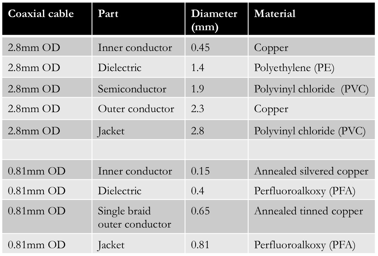
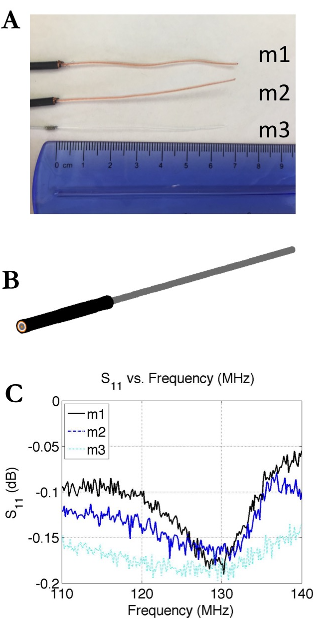
Hardware: We built two prototypes by using 50Ω coaxial cable (G_01130_HT-03, HUBER+SUHNER) with outer diameter (OD) 2.8 mm (m1 and m2), as well as a third prototype (m3) with an ultra-miniature coaxial cable with OD 0.81mm (D08101T5GT, Wellshow Technology) (Table 1). We removed the outer shielding and jacket, leaving a quarter wavelength, 6.5 cm in water at 3T (11), with total length about 30.5 cm (Fig. 1A). We measured the resonant frequency using an E5061A network analyzer (Agilent Technologies) and calculated the Q-factor of a least-squares polynomial fit curve using MATLAB (MathWorks, Natick, MA).
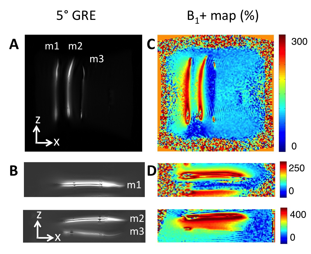
Image Acquisition: We acquired the following scans parallel and perpendicular to the B0 field in water doped with CuSO4 on a 3T MR750w scanner (GE Healthcare) using the following parameters: α = 5°, gradient echo (GRE) sequence with TE = 3.7 ms, TR = 100ms, matrix 256 × 256, FOV 30–36 cm, and 5 mm slice thickness, as well as gradient echo Bloch-Siegert B1+ maps (12,13) with α = 5°, TE = 14ms, TR = 48 ms, matrix 128 × 128, 30–36 cm, and 5 mm slice thickness. The B1+ maps were scaled to a selected ROI in the background of the water.
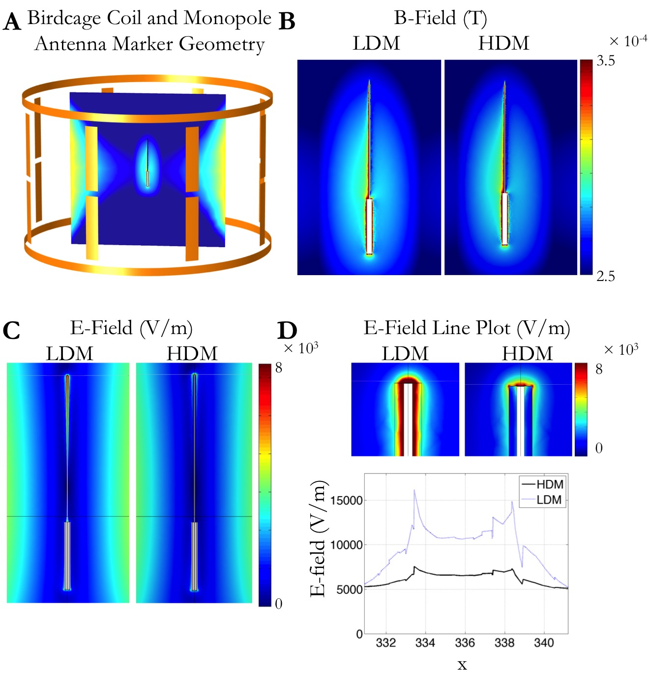
Simulations: Using finite element method software (COMSOL 5.2a, Burlington, MA), we modeled the 2.8mm OD monopole antenna marker in a cylinder of water, using a 8-rung birdcage coil with a 48cm diameter and 30cm height to provide transmit RF excitation for inductive coupling to the marker. A parametric sweep was performed to determine the optimal capacitance of the coil capacitors for magnetic field homogeneity. Next, we modeled the electromagnetic fields of monopole antenna marker (Fig. 1B) with the following properties. For the low dielectric material polyethylene, we used a relative permittivity εr = 2.1, relative permeability μr = 1, and electrical conductivity σ = 0.6 S/m. For the HDM, we used the properties from a prior study reporting properties of sintered high-permittivity ceramic (BaTiO3) beads in deuterated water (8): εr = 515 and σ = 0.35 S/m, and μr = 1.
Results
We tuned the monopole antenna marker to the Larmor frequency and measured approximate Q-factors of 11.7, 11.1, and 7.6 for m1, m2, and m3, respectively (Fig. 1C). The monopole antenna marker demonstrated good signal in both orientations for the GRE sequence (Fig. 2A-B) and mean scaled B1+ map of the three prototypes were 272%, 252%, and 198% respectively in the parallel orientation (Fig. 2C-D). The simulations of the magnetic flux density norm (Fig. 3A) demonstrated a similar signal pattern to that in the experimental B1+ maps (Fig. 3B). Comparing the simulations of the monopole antenna marker coated with HDM to LDM, there was a 1.6 factor reduction of the electric fields using the high permittivity dielectric coating (Fig. 3C) at the midpoint (Fig. 3D).Discussion and Conclusion
Design of resonant markers using monopole antenna technology for localizing the catheter was proposed and investigated, demonstrating good signal. The electric field distributions suggest that using high permittivity dielectric materials might be a possible approach to reducing the potential tissue heating during the imaging procedure. The monopole antenna marker was compact and easy to build, indicating its feasibility for interventional MR guidance.Acknowledgements
This work is supported by NIH grant UL1 TR001872-01.References
1. Krug J, Will K, Rose G. Simulation and experimental validation of resonant electric markers used for medical device tracking in magnetic resonance imaging. 2010 Annual International Conference of the IEEE Engineering in Medicine and Biology. IEEE; 2010. p. 1878–81.
2. Thorne BR, Lillaney P, Losey AD, et al. Micro Resonant Marker for Endovascular Catheter Tracking in Interventional MRI: In Vitro Imaging at 3T. ISMRM. 2014. p. 2327.
3. Kuehne T, Weiss S, Brinkert F, et al. Catheter visualization with resonant markers at MR imaging-guided deployment of endovascular stents in swine. Radiology. 2004;233:774–80.
4. Quick HH, Zenge MO, Kuehl H, et al. Interventional magnetic resonance angiography with no strings attached: Wireless active catheter visualization. Magn Reson Med. 2005;53(2):446–55.
5. Celik H, Atalar E. Reverse polarized inductive coupling to transmit and receive radiofrequency coil arrays. Magn Reson Med. 2012;67(2):446–56.
6. Hong SM, Park JH, Woo MK, et al. New design concept of monopole antenna array for UHF 7T MRI. Magn Reson Med. 2014;71(5):1944–52.
7. Yan X, Zhang X, Wei L, Xue R. Design and Test of Magnetic Wall Decoupling for Dipole Transmit/Receive Array for MR Imaging at the Ultrahigh Field of 7T. Appl Magn Reson. 2014;46(1):59–66.
8. Luo W, Lanagan MT, Sica CT, et al. Permittivity and performance of dielectric pads with sintered ceramic beads in MRI: Early experiments and simulations at 3 T. Magn Reson Med. 2013;70(1):269–75.
9. Venkateswaran M, Unal O, Hurley S, et al. Modeling Endovascular MRI Coil Coupling with Transmit RF Excitation. IEEE Trans Biomed Eng. 2016;9294(c):1–1.
10. Ellersiek D, Fassbender H, Bruners P, et al. A monolithically fabricated flexible resonant circuit for catheter tracking in magnetic resonance imaging. Sensors Actuators, B Chem. Elsevier B.V.; 2010;144(2):432–6.
11. Schmilz BL, Aschoff AJ, Hoffmann MHK, Grön G. Advantages and pitfalls in 3T MR brain imaging: A pictorial review. American Journal of Neuroradiology. 2005. p. 2229–37.
12. Sacolick LI, Wiesinger F, Hancu I, Vogel MW. B1 mapping by Bloch-Siegert shift. Magn Reson Med. 2010;63(5):1315–22. 13. Khalighi MM, Rutt BK, Kerr AB. RF pulse optimization for Bloch-Siegert B+1 mapping. Magn Reson Med. 2012;68(3):857–62.
Figures