0517
Simultaneous Multi Slice Imaging using Matrix Gradient Coils1Department of Radiology, Medical Physics, University Medical Center, Freiburg, Germany, 2Athinoula A. Martinos Center for Biomedical Imaging, Department of Radiology, Massachusetts General Hospital, Charlestown, MA, United States
Synopsis
Novel SMS techniques become possible by applying specially designed spatial encoding magnetic fields (SEMs) during RF excitation or read out. Two new methods have been implemented using a matrix gradient coil.
INTRODUCTION
Simultaneous multi slice techniques (SMS) [1] are one way to speed up the inherently slow MR image acquisition by deploying parallel imaging techniques to separate signals from excited sub-volumes. Different shapes of nonlinear spatial encoding magnetic fields (where linear SEMs are known as gradients) allow for spatially-dependent manipulation of phase and frequency in a more flexible manner. This may be used to deploy SMS in a different way. The authors recently presented a 84 channel matrix gradient coil [2,3] that allows one to generate nearly arbitrary field shapes. This study demonstrates the feasibility of two straightforward SMS approaches by employing the matrix gradient coil.
METHODS
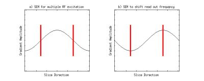
The first method utilizes a spatially-oscillating field along the slice direction to simultaneously excite multiple slices. A sinusoidally-varying field has approximately linear segments with the same gradient strengths. By playing out such SEM field for slice selection, multiple slices with the same thickness and uniformly excited voxels can be achieved with standard RF-pulses. A similar method has already been recently presented by employing a dedicated z-gradient array [4]. A depiction of this method is displayed in fig.1 a).
Second, the signals from the excited slices may be shifted during readout, similar to View Angle Tilting [5]. An effective signal separation can be achieved by shifting the same spatially-oscillating field such that approximately constant minima and maxima (with zero gradients) are played out at the excited slice positions during readout. This results in a spatially-dependent frequency shift for slices from different locations without undesired distortions and dephasing as in View Angle Tilting. A depiction is given in fig.1 b).
Experiments were performed on a 3T scanner (Siemens Trio, a Tim system) equipped with additional gradient insert hardware which was developed and built in-house consisting of the following components: 84-channel matrix gradient coil [2,3]; controller, clock distribution board, 12-channel digital-to-analog converter [6] and a 12-channel gradient power amlifier setup (IECO, XPA-150-350). The gradient coil was clustered into 12 channels, each containing five elements along z, to obtain maximum gradient strength in a transversal slice. Simulations and data processing was performed in Matlab (Natick, USA). Pulse sequences were programmed in Pulseq [7] to simultaneously control the MR scanner and the additional hardware. For demonstration experiments both methods were experimentally verified independently by imaging a carrot using a gradient echo sequence with TE/TR of 15/200ms and a flip angle of 20°.
RESULTS
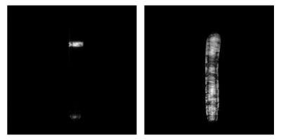
Multi slice excitation is displayed in fig.2. A through-slice view displays the two simultaneously excited slices. This was achieved with a single RF sinc pulse applied in presence of a SEM with the spatially-oscillating shape.
Through slice and fully encoded views at different SEM strengths played out during readout are shown in fig.3 and fig.4, accordingly. For higher amplitudes a larger separation between the two excited slices can be seen. The ghosting artifacts visible in fig.3 are believed to be related to stimulated echoes due to insufficient spoiling.
DISCUSSION
Two methods for simultaneous multi slice imaging have been successfully demonstrated using a matrix gradient coil.
Due to our implementation of the matrix gradient coil and drivers used for the proof-of-principle experiments the two fields required can be generated. However, the fields cannot be generated currently at the same positions to combine the two methods with the limits set by the amplifiers used. Additionally, the matrix coil was not optimized for linearity or homogeneity in a specific region, but for local gradient strength. Therefore the homogeneous regions for both methods are limited. For enhanced field-of-views occurring distortions may be be corrected for in a straight forward manner based on the known SEM. For future designs of matrix gradient coils the requirements to combine both SMS techniques presented here may be considered in the design stage.
Simultaneous Multi Slice excitation without additional SAR becomes possible by employing spatially-oscillating SEM fields. Parallel readout based on a spatially-dependent frequency shift results in a fully sampled k-space without under-sampling and associated SNR losses. No additional information such as RF-receive profiles or calibration scans are necessary. A spatially-dependent frequency shift may be described as an extension of View Angle Tilting without unwanted distortions or dephasing effects. However, both presented methods rely on non-standard gradient hardware with certain requirements regarding flexibility and homogeneity.
Acknowledgements
This work was supported by the European Research Council grant 282345 ’RANGEmri’.References
[1] Setsompop, K., Gagoski, B. A., Polimeni, J. R., Witzel, T., Wedeen, V. J. and Wald, L. L. (2012), Blipped-controlled aliasing in parallel imaging for simultaneous multislice echo planar imaging with reduced g-factor penalty. Magn. Reson. Med., 67: 1210–1224. doi:10.1002/mrm.23097
[2] Littin, et al. (2016), Shielded Matrix Gradient Coil. Proc. 23th ISMRM Congress, Toronto (2015): 1022.
[3] Littin, et al. (2016), Implementation of an 84 Channel Actively Shielded Matrix Gradient Coil. Proc. 24th ISMRM Congress, Singapore (2016): 3561.
[4] K. Ertan, S. Taraghinia, A. Sadeghi, E. Atalar. A Z-gradient array for spatially oscillating magneticfields in multi-slice excitation. Proc. ESMRMB Congress (2016) 29 (Suppl 1):S75–S76
[5] Butts K, Pauly J, Gold G, Reduction of Blurring in View
Angle Tilting MRI with Multiple View Angle Tilting Readouts, MRM, 2005
Feb;53(2):418-24.
[6] Yu, et al.(2016), A Multi-Channel Gradient Driver System for Matrix Gradient Coils. Proc. 24th ISMRM Congress, Singapore
(2016): 3548
[7] Layton, KJ, Kroboth, S, Jia, F, Littin, S, Yu, H, Leupold, J, Nielsen,JF, Stcker, T, and Zaitsev, M. Pulseq: A rapid and hardware-independentpulse sequence prototyping framework. Magnetic Resonance in Medicine2016:n/a–n/a.
Figures

Figure 1: Field shapes of spatial magnetic encoding fields (SEMs) required for the two different SMS techniques. a) A cosine-shaped SEM (black) allows to excite multiple slices (red) by playing out a single RF pulse. b) Playing out a sine-shaped SEM during read-out manipulates the frequency such that each slice can be received in different frequency bands.


Figure 3: Through-slice view demonstrating the dependence of the shift of individual slices on the applied field amplitude. Image a) was acquired without additional gradient during read out. For increasing field amplitude the slices are shifted accordingly (b) and c)).

Figure 4: Axial view through the carrot demonstrating the same dependence as displayed in Figure 3. The amplitude dependent shift effect can be observed in the encoded image.