0389
Velocity Encoded and Compensated Multi-Spoke RF Pulses for Flow Quantification at Ultra-High Fields1Medical Physics in Radiology, German Cancer Research Center (DKFZ), Heidelberg, Germany, 2Institute for Forensic Medicine and Traffic Medicine, University Hospital Heidelberg, Heidelberg, Germany, 3Physikalisch-Technische Bundesanstalt (PTB), Braunschweig and Berlin, Germany
Synopsis
In this work we present and demonstrate a novel technique to generate multi-spoke RF excitation with arbitrary zeroth and first gradient moments, allowing for clean flow imaging without errors. The RF pulses are demonstrated in flow phantoms and in-vivo at 7 Tesla, paving the road for 4D flow imaging using pTX spoke excitation.
Purpose / Introduction
Three-dimensional tailored radiofrequency (RF) pulses, termed "multi-spoke" RF pulses [1], have been applied in Ultra-High-Field (UHF) MRI to successfully address spatial flip angle (FA) heterogeneities [2,3]. Such multi-spoke RF pulses, consisting of a train of successive sinc-shaped RF pulses, however, cannot be applied straightforwardly for UHF flow quantification/compensation, since the generated slice profile is spatially shifted and shows degraded profile ramps in the presence of flow [4]. Here we present and demonstrate a novel technique to generate multi-spoke RF excitation with arbitrary zeroth and first gradient moments, allowing for clean flow imaging without errors. The RF pulses are demonstrated in flow phantoms and in-vivo at 7 Tesla, paving the road for 4D flow imaging using pTX spoke excitations.Theory
For simplicity, we consider 3D slab-selective excitations with flow encoding/compensation in the slab direction only, but the principle is also applicable to 3D encoding. At first, non-flow-compensated 3D imaging is regarded, where the zeroth gradient moment $$$m_0=\int_{t_0}^{t_{end}}G(t)dt$$$ is controlled during imaging for spatial encoding in the phase-encoding (PE) and partition-encoding (SL) directions. Here $$$t_0$$$ is the isodelay time point (typically RF pulse center), and $$$t_{end}$$$ is the end of the last gradient. In this case, the first moment $$$m_1=\int_{t_0}^{t_{end}}G(t)\cdot{t\,}dt$$$ is not constant but increases line-by-line, leading to velocity-dependent spatial shifts (see Fig. 1a). Flow compensation (encoding) is typically achieved using bipolar gradients with zero (constant non-zero) $$$m_1$$$ moment for all lines (Fig.1b), leading to correct profiles. According to the superposition principle in the small tip-angle regime [5], multiple isodelay points $$$t_0^i$$$ exist, if multi-spoke pulses are considered, requiring individual $$$m_1$$$ adjustment for each subpulse.Methods
Flow compensation and encoding is realized for multi-spoke pulses by replacing the slice rewinders (Fig.2c) by bipolar gradients with identical $$$m_0$$$. A set of linear equations is set up to calculate the gradient amplitudes $$$G_a^i$$$ and $$$G_b^i$$$ and durations $$$t_a^i$$$ and $$$t_b^i$$$ for spoke $$$RF^i$$$ such that the zeroth moment $$$m_0^i=m_0$$$ and the first moment $$$m_1^i=m_1$$$ for all spokes $$$i$$$. Since the system is underdetermined, a solution leading to minimal total spoke duration is searched. The calculation was implemented into a standard gradient echo sequence utilizing two spokes and applied at 7 Tesla (Siemens Healthcare, Erlangen, Germany) using a 28-channel knee coil (Quality Electrodynamics, Mayfield, USA) and a custom flow phantom containing two pipes with constant flow velocity (Fig.3). Imaging parameters: matrix=160x160x120, resolution=1x1x1mm3, TE1/TE2=9.47/5.12ms. The slab field-of-view (120mm) was four times the excitation slab thickness (30mm) to analyze slice profile performance. Slice shifts were measured for i) no compensation (Fig.2a), ii) standard compensation (Fig.2b), iii) spoke-individual compensation (Fig.2c). The same protocol and hardware were applied with cardiac triggering to measure shifts in-vivo in the femoral artery during peak systole (248ms delay after RR). A second 2-spoke protocol with 2 measurements having different $$$m_1$$$ of 1.17mT/m$$$\cdot$$$ms² and 0mT/m$$$\cdot$$$ms²(corresponding to VENC=100cm/s) was applied and compared to a standard flow imaging protocol.Results
Figure 3 shows successful suppression of flow-induced artifacts using the presented flow compensation technique for 2 spokes. Shifts of -2.83±0.05 mm and 1.65±0.05mm were minimized to -0.17±0.05mm and 0.12±0.05mm. Similar results were obtained in-vivo with 2 spokes as illustrated in Fig.4. Quantification of the peak velocity during systole was found to be similar to the standard vendor-provided flow encoding sequence (Fig.5a+b). Difference in peak velocity was 3.0%, and mean velocity deviation within the artery was 4.7cm/s.Discussion / Conclusion
A method for flow compensated and flow encoded multi-spoke RF pulses has been presented and successfully applied in phantoms and in-vivo. The principle was shown here only for monopolar spokes and for flow in the slab direction; however, simulations and initial results show that the same principle can be applied for bipolar spokes and also for quantification in the PE or readout directions. Furthermore, this principle allows different non-zero moments $$$m_0^i$$$ between spokes, thus enabling the typical "gradient blips" of spoke excitation to address in-plane FA variations in combination with multi-channel RF shimming for each spoke. Thus, the work presented here illustrates a method for how to perform pTX-spoke-enabled 3D / 4D flow imaging.Acknowledgements
No acknowledgement found.References
[1] Saekho, S., Yip, C.-y., Noll, D. C., Boada, F. E. and Stenger, V. A. (2006), Fast-kz three-dimensional tailored radiofrequency pulse for reduced B1 inhomogeneity. Magn Reson Med, 55: 719–724. doi: 10.1002/mrm.20840
[2] Setsompop, K., Alagappan, V., Gagoski, B., Witzel, T., Polimeni, J., Potthast, A., Hebrank, F., Fontius, U., Schmitt, F., Wald, L. L. and Adalsteinsson, E. (2008), Slice-selective RF pulses for in vivo Bmath image inhomogeneity mitigation at 7 tesla using parallel RF excitation with a 16-element coil. Magn. Reson. Med., 60: 1422–1432. doi:10.1002/mrm.21739
[3] Schmitter, S., DelaBarre, L., Wu, X., Greiser, A., Wang, D., Auerbach, E. J., Vaughan, J. T., Ugurbil, K. and Van de Moortele, P.-F. (2013), Cardiac imaging at 7 tesla: Single- and two-spoke radiofrequency pulse design with 16-channel parallel excitation. Magn. Reson. Med., 70: 1210–1219. doi:10.1002/mrm.24935
[4] Schmidt, S., Flassbeck, S., Breithaupt, M., Ladd, M. E., Schmitter, S. (2016), On the Performance of Multi-Spoke RF Pulses in the Presence of Laminar Flow - a Simulation Study. Magn. Reson. Mat. Phys. Biol. Med., 29(1 Supplement), 2016. ESMRMB 2016, 33rd Annual Scientific Meeting, Vienna, AT, September 29 - October 1, contribution no. 381.
[5] Pauly, J., Nishimura, D., Macovski, A. (1989). A k-space analysis of small-tip-angle excitation. J. Magn.
Reson. (1969), 81(1), 43-56.
Figures
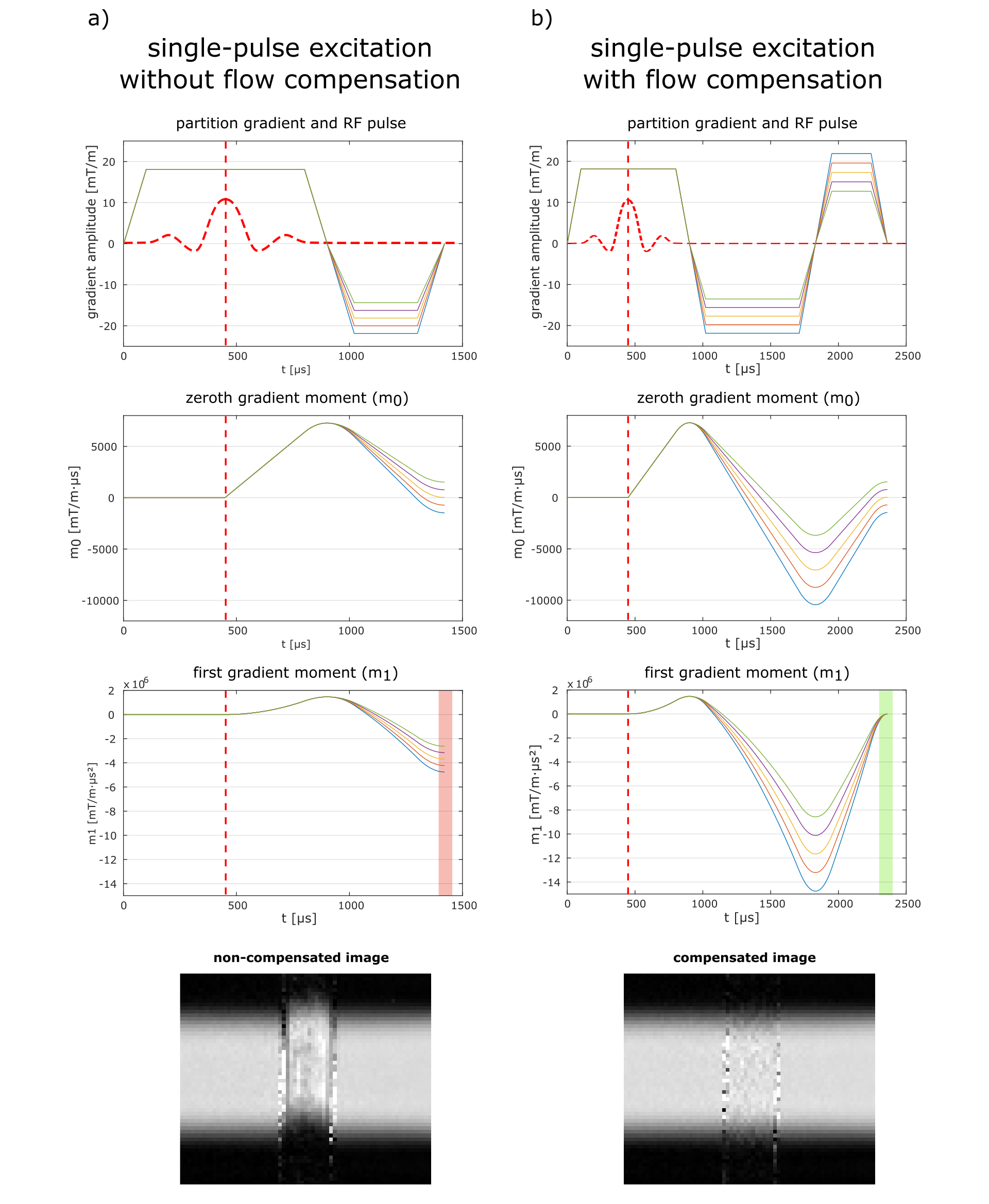
Figure 1:
a) RF and gradient waveforms of a single-pulse excitation and corresponding $$$m_0$$$ and $$$m_1$$$ without flow compensation. The variation of $$$m_1$$$ over the acquisition k-space (red area) leads to velocity dependent spatial shifts as shown in the phantom measurement.
b) By applying bipolar gradients, adapted for each line, constancy of the first gradient moment over the acquisition k-space (green area) can be achieved and thereby correct slice profiles can be acquired.
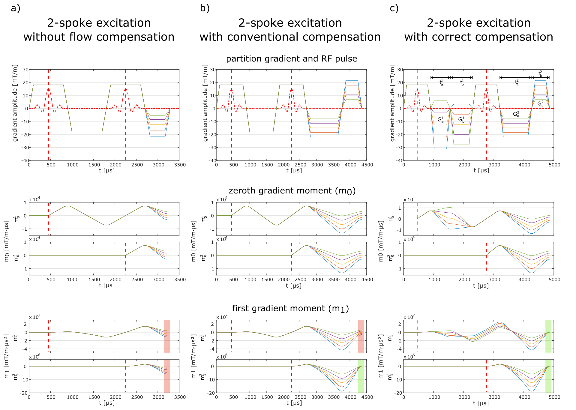
Figure 2:
a) RF and gradient waveforms of a 2-spoke excitation and corresponding $$$m_0$$$/$$$m_1$$$ without flow compensation. For both pulses $$$m_1$$$ varies over the acquisition k-space (red area) leading to spatial shifts of the magnetization excited by both pulses.
b) With conventional compensation $$$m_1$$$ of the second pulse (green area) but not of the first pulse (red area) can be kept constant. Therefore, the magnetization excited by the first pulse will still appear shifted in the image.
c) Applying correct flow compensation to a 2-spoke excitation results in constant $$$m_1$$$ for both pulses over the entire acquisition k-space (green areas).
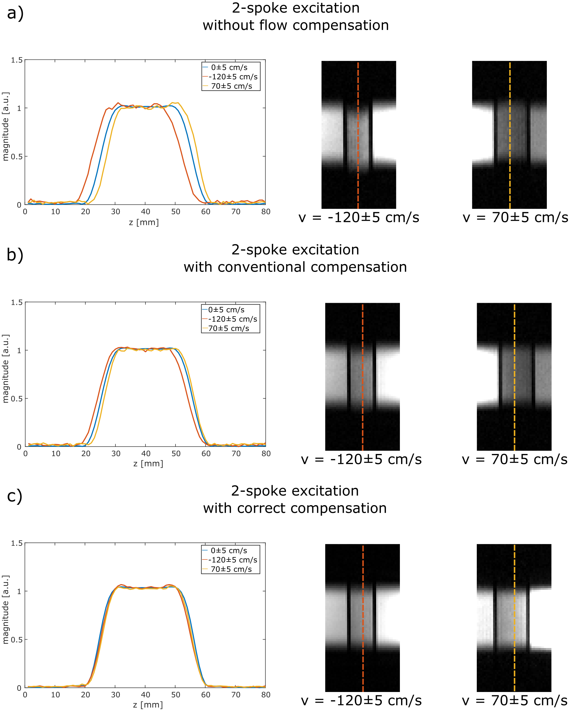
Figure 3:
Cross-section through a measured slice in a static region (blue) and in two pipes within a flow phantom containing flowing water (red & yellow). Without flow compensation (top), slice center shifts of -2.83±0.05 mm and 1.65±0.05mm are observed. Applying conventional flow compensation to the monopolar 2-spoke excitation (middle) results in slice center shifts of-1.29±0.05 mm and 0.84±0.05mm. Applying flow compensation optimized for the monopolar 2-spoke excitation (bottom), these shifts are reduced to -0.17±0.05mm and 0.12±0.05mm.
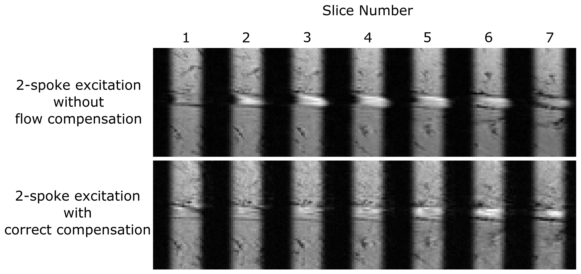
Figure 4:
In-vivo images of the femoral artery of a healthy volunteer acquired with a monopolar 2-spoke excitation without and with correct flow compensation. The flow-related slice profile degradation, present in the images without flow compensation, is suppressed in the correctly compensated images.
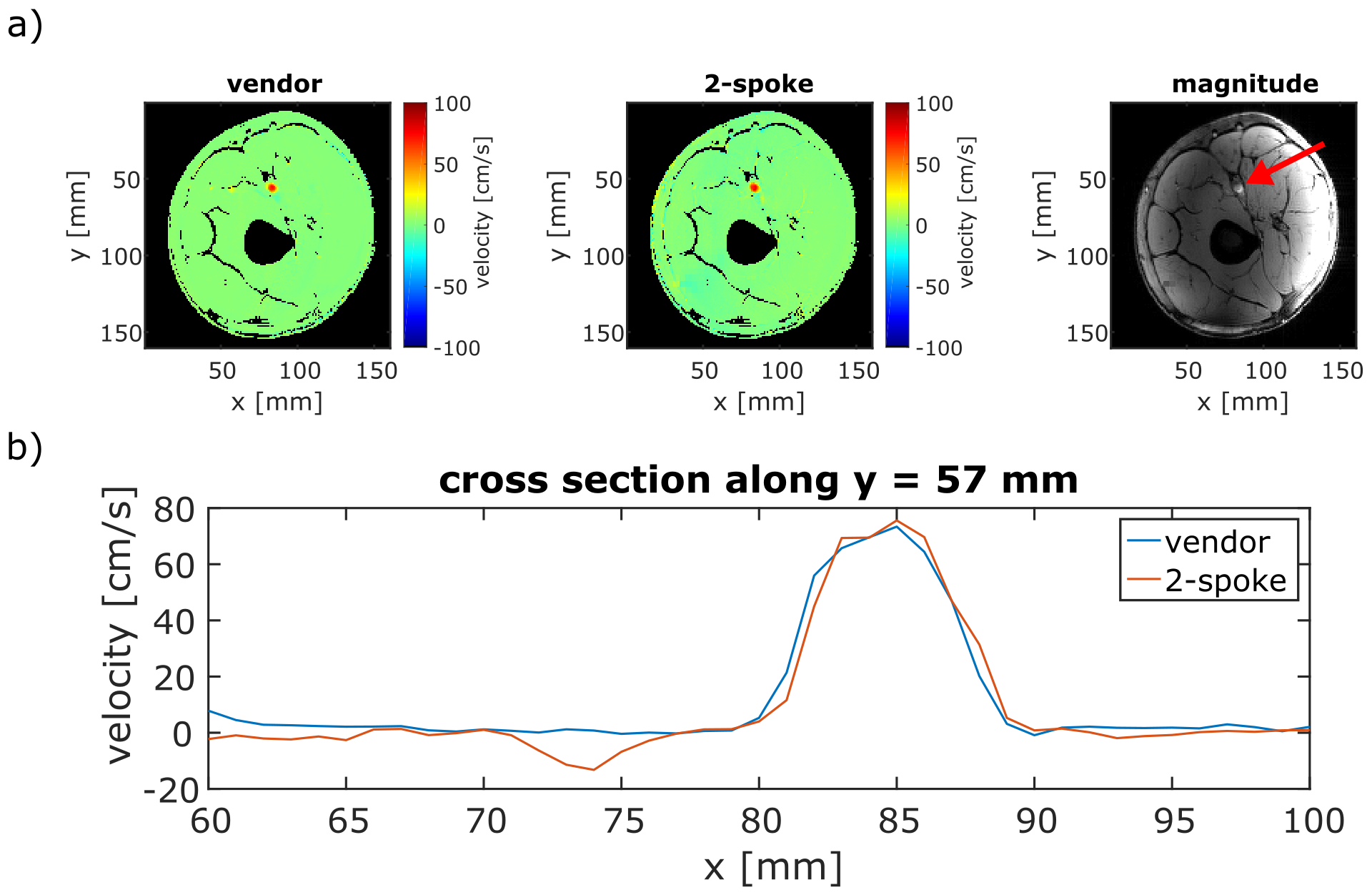
Figure 5:
a) In-vivo velocity maps (axial slice, through-plane velocity encoded) of the femoral artery of a healthy volunteer acquired with a vendor-provided sequence (left) and with a monopolar 2-spoke excitation (middle). The velocity maps are noise masked based on an amplitude image (right). The red arrow indicates the femoral artery in the amplitude image.
b) Cross section through the velocity profile of the femoral artery. Difference in peak velocity is 3.0%, and mean velocity deviation within the artery is 4.7cm/s.