0385
Improved signal uniformity for balanced steady-state free precession by employing Direct Signal Control parallel transmission1Translational and Molecular Imaging Institute, Icahn School of Medicine at Mount Sinai, New York, NY, United States
Synopsis
We present a method to minimize signal intensity variations observed when performing balanced steady state free precession imaging in non-uniform B0 and B1+ fields. This is achieved by harnessing parallel transmission, with RF shims calculated in order to produce the most uniform signal for the desired tissues given measured B0 and B1+ field maps.
Purpose
Balanced Steady-State Free Precession (bSSFP)$$$^1$$$ offers ultra-high resolution structural$$$^{2,3}$$$ and functional$$$^4$$$ imaging at ultra-high field (UHF), but is impaired by $$$B_0$$$-inhomogeneity, transmit field ($$$B_1^+$$$)-inhomogeneity and power deposition. These effects result in SAR-limited UHF-bSSFP acquisitions that produce images with uneven signal/contrast.
Many methods have been developed to mitigate the effects of $$$B_0$$$-inhomogeneity on bSSFP$$$^{5-9}$$$, and bSSFP can incorporate parallel transmission (PTx) $$$B_1^+$$$-inhomogeneity correction strategies$$$^{3,10}$$$. Here we propose a novel approach to mitigate $$$B_0$$$ and $$$B_1^+$$$-inhomogeneity for bSSFP in a single unified manner. We apply Direct Signal Control$$$^{11,12}$$$ to bSSFP for the first time, harnessing PTx to improve image uniformity in spite of field inhomogeneities.
Methods
The bSSFP steady-state magnetization at TE=TR/2 with flip angle $$$\alpha$$$ and 0-180° phase cycling with relaxation times $$$T_1$$$ and $$$T_2$$$ and off-resonance $$$d\omega$$$ is given below ($$$\mathbf{R}_\beta$$$=rotation matrix of angle $$$\beta$$$, $$$\mathbf{P}_t$$$=precession/$$$T_2$$$-decay matrix for duration $$$t$$$, $$$\mathbf{b}$$$=$$$T_1$$$-recovery vector)$$$^{13}$$$.
$$\mathbf{M}(TR,\alpha,d\omega,T_1,T_2)=\mathbf{P}_{TR/2}[\mathbf{I}-\mathbf{R}_{\alpha}\mathbf{P}_{TR}\mathbf{R}_{-\alpha}\mathbf{P}_{TR}]^{-1}[\mathbf{R}_{\alpha}\mathbf{P}_{TR}\mathbf{R}_{-\alpha}\mathbf{b}+\mathbf{R}_{\alpha}\mathbf{b}]$$
$$$B_0$$$/$$$B_1^+$$$ inhomogeneity results in spatially variable fields (i.e. $$$\alpha=\alpha_j$$$, $$$d\omega=d\omega_j$$$; $$$j$$$=voxel index), causing spatially variable signal $$$f(TR,\alpha_j,d\omega_j,T_1,T_2)=\sqrt{M_x^2+M_y^2}$$$. We propose exploiting additional freedom offered by multiple ($$$N_{tx}$$$) transmitters to achieve signal uniformity by solving the optimization problem below ($$$\Phi$$$=cost function to be minimized, $$$\mathbf{w}$$$=$$$N_{tx}$$$x1 complex vector of RF shims, $$$\alpha_j^k$$$=flip angle profile of transmitter $$$k$$$, $$$i$$$=1,…,$$$N_{tiss}$$$ is an index of included tissues, $$$d_i$$$=desired signal, $$$P_{lim}$$$=RF power limit used as a surrogate for SAR).
$$\newcommand{\abs}[1]{\left|#1\right|}\underset{\bf{w}}{\text{minimize}}\enspace\Phi=\sum_{i=1}^{N_{tiss}}\sum_{j=1}^{N_{vox}}\abs{d_i-f\left(TR,\sum_{k=1}^{N_{tx}}\alpha^k_jw^k,d\omega_j,T_1^i,T_2^i\right)}^2\enspace\text{subject}\;\text{to}\enspace\mathbf{w}^*\mathbf{w}\leq\text{P}_{lim}$$
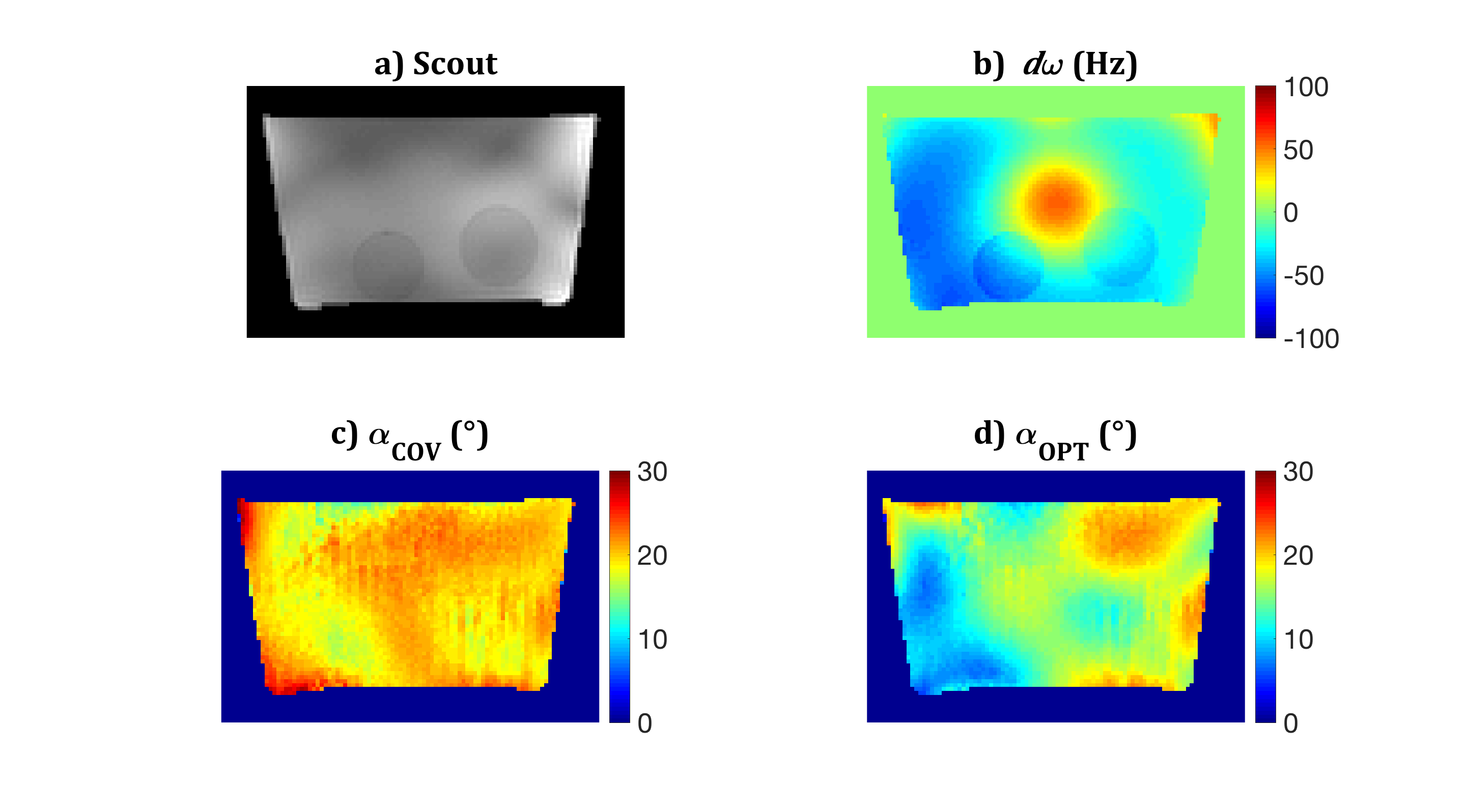
This approach was tested experimentally. Measurements were performed on a Siemens Magnetom-7T with an eight-channel transmit/receive head coil (Rapid Biomedical). A phantom was constructed containing Magnevist-doped saline ($$$T_1$$$=1236ms, $$$T_2$$$=611ms) with two chambers of 0%-fat milk ($$$T_1$$$=1949ms, $$$T_2$$$=91ms) and a spherical air cavity (diameter=40mm) to induce $$$B_0$$$-inhomogeneity. Images were acquired in a single transverse slice with FOV=200x112.5mm, located 30mm superior to the cavity. Flip angle profiles were obtained by relative $$$B_1^+$$$ mapping$$$^{14,15}$$$ and multi-angle absolute $$$B_1^+$$$ mapping$$$^{16}$$$. $$$B_0$$$ shimming utilized a manufacturer-provided protocol (WIP-452G). The center frequency was set to minimize the maximum $$$|d\omega_j|$$$. $$$B_0$$$ mapping was performed with a multi-echo SPGR (TEs=2,4,…,10ms).
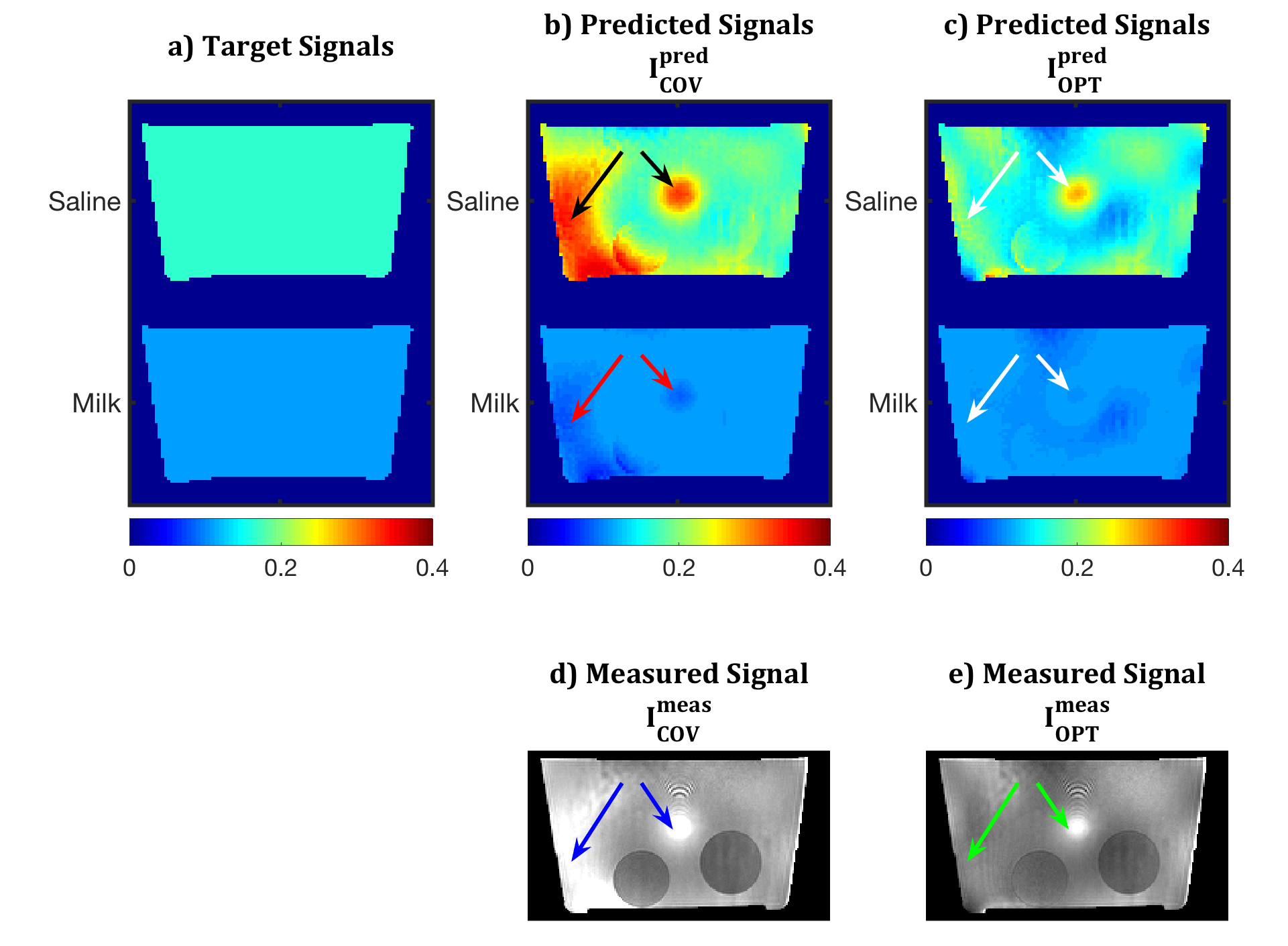
Two RF shims were used for bSSFP acquisitions (vox=2x2x1mm, TR=6.7ms, BW=685Hz/pix). The first, $$$\mathbf{w}_{COV}$$$, producing flip angle map $$$\alpha_{COV}$$$, was obtained from a Coefficient-of-Variation (COV) optimisation$$$^{17}$$$, and scaled to achieved an average $$$\alpha$$$=20° (chosen to meet transmitter RF power limits). The second, $$$\mathbf{w}_{OPT}$$$, producing flip angle map $$$\alpha_{OPT}$$$, was obtained from the proposed method. All field information was passed to the routine for calculation, target signals $$$d_i$$$ were set as the signals obtained on-resonance with $$$\alpha$$$=20° (i.e. $$$f(TR,20^\circ,0,T_1^i,T_2^i)$$$), and $$$P_{lim}$$$=$$$\mathbf{w}_{COV}^*\mathbf{w}_{COV}$$$. An initial search was performed using 100,00 random RF shims; the 20 best were used for initialisation of the Matlab routine fmincon. $$$\mathbf{w}_{OPT}$$$ was chosen as the best solution. The bSSFP acquisitions were corrected for receiver bias to produce $$$I_{COV}^{meas}$$$ and $$$I_{OPT}^{meas}$$$, which were compared to the predicted images for each substance and method, $$$I_{COV,i}^{pred}$$$ and $$$I_{OPT,i}^{pred}$$$.
Results
The $$$B_0$$$ map (Fig.1b) shows a central perturbation (+55Hz) due to the air cavity. The minimum frequency is -65Hz; note the localized ~10Hz artifact due to the chemical shift of milk. $$$\alpha_{COV}$$$ is more uniform than $$$\alpha_{OPT}$$$ (Figs.1c/d; standard deviations of 1.9° and 3.8° respectively). Whilst in conventional sequences $$$\alpha_{COV}$$$ would produce a more uniform image than $$$\alpha_{OPT}$$$, Fig.2 demonstrates that the converse is true for bSSFP in this scenario.
$$$I_{COV}^{pred}$$$ (Fig.2b) has signal hyper/hypo-intensities (black/red arrows) in regions of large $$$B_0$$$-inhomogeneities. These also appear in $$$I_{COV}^{meas}$$$ (Fig.2d, blue arrows). $$$I_{OPT}^{pred}$$$ shows reduced signal inhomogeneity (Fig.2c, white arrows), which is confirmed by experiment ($$$I_{OPT}^{meas}$$$, Fig.2e, green arrows).
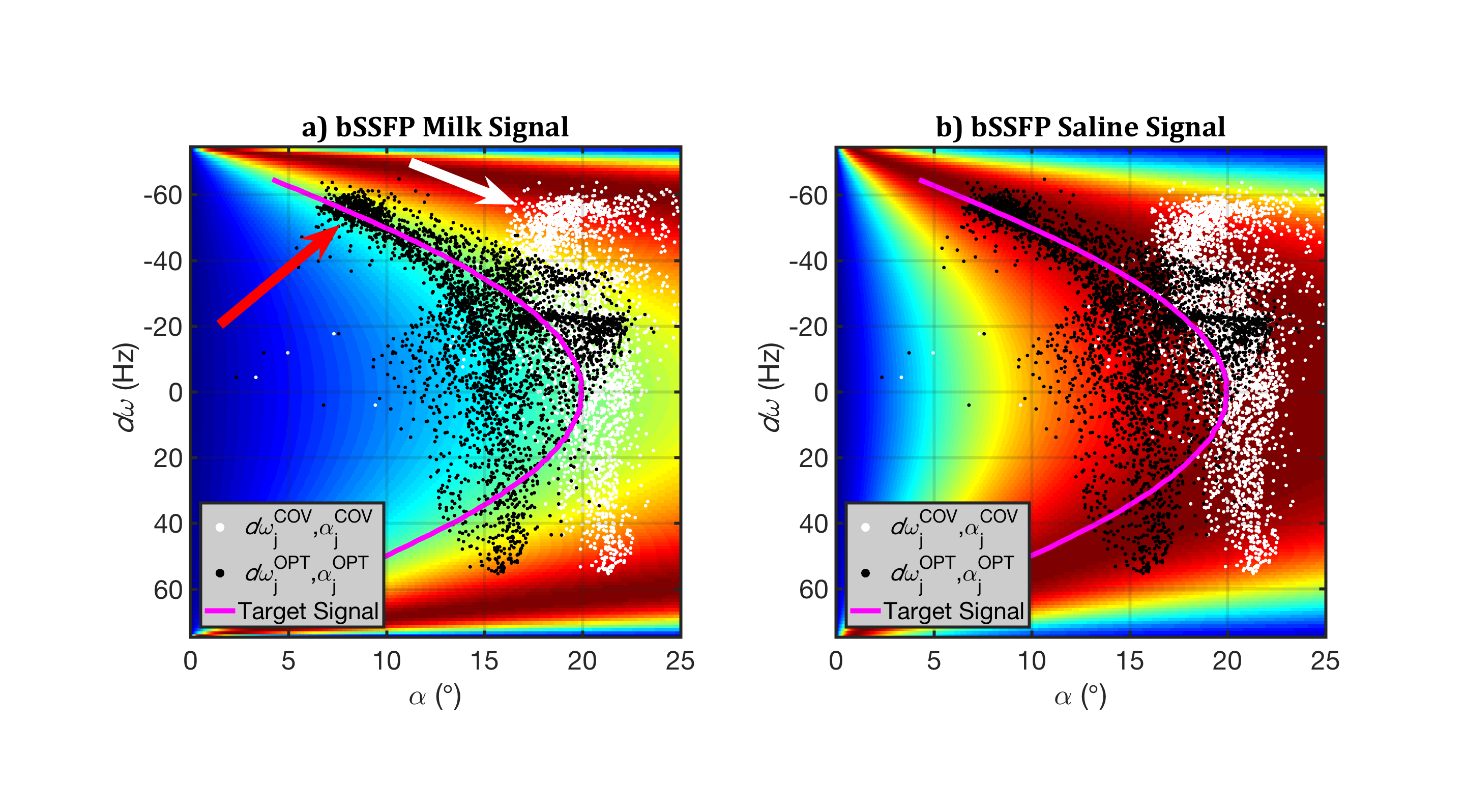
Figure 3 gives further insight. Each image shows the predicted bSSFP signal as a function of $$$d\omega$$$ and $$$\alpha$$$ (Fig.3a, milk; Fig.3b, saline). The desired signal $$$d_i$$$ is indicated in magenta; note that lower $$$\alpha$$$ is required to obtain $$$d_i$$$ when $$$d\omega$$$≠0. Each overlaid scatter-point corresponds to a voxel (white, $$$I_{COV}^{pred}$$$; black, $$$I_{OPT}^{pred}$$$), placed according to its $$$d\omega_j$$$ and corresponding $$$\alpha_j$$$. Signals from $$$I_{COV}^{pred}$$$ exhibit less variation along the $$$\alpha$$$-axis as $$$\alpha_{COV}$$$ is uniform, but off-resonance distributes the points along the $$$d\omega_j$$$-axis, resulting in non-uniform signal (white arrow). However, our proposed technique alters $$$\alpha_{OPT}$$$ so that signals from $$$I_{OPT}^{pred}$$$ are closer to the desired signal (red arrow).
Finally, the power ratio $$$\mathbf{w}_{OPT}^*\mathbf{w}_{OPT}$$$/$$$\mathbf{w}_{COV}^*\mathbf{w}_{COV}$$$=0.52; whilst this implies reduced SAR, further experiments are required to see if this is a reproducible feature of the proposed method.
Discussion and Conclusions
Joint $$$B_0$$$/$$$B_1^+$$$-inhomogeneity correction for bSSFP using PTx has been demonstrated for the first time at 7T. We anticipate incorporating $$$B_0$$$ shim calculation into the optimization and using more transmitters will yield further benefits. Future work will test the method in-vivo, incorporate global/local SAR limits, and generalize the technique for multi-TR bSSFP.Acknowledgements
This work was supported by National Institutes of Health under NCI R01 CA202911, the Icahn School of Medicine Capital Campaign, the Translational and Molecular Imaging Institute and the Department of Radiology, Icahn School of Medicine at Mount Sinai. We also thank Prof. Joseph V. Hajnal and Dr. Shaihan Malik for useful discussions.References
1. Miller, K. L., Hn Tijssen, R., Stikov, N. & Okell, T. W. Steady-state MRI: methods for neuroimaging. Imaging Med 3, 93–105 (2011).
2. Zeineh, M. M. et al. Ultrahigh-resolution imaging of the human brain with phase-cycled balanced steady-state free precession at 7 T. Invest. Radiol. 49, 278–89 (2014).
3. Hahnemann, M. L. et al. Non-enhanced magnetic resonance imaging of the small bowel at 7 Tesla in comparison to 1.5 Tesla: First steps towards clinical application. Magn. Reson. Imaging 34, 668–673 (2016).
4. Scheffler, K. & Ehses, P. High-resolution mapping of neuronal activation with balanced SSFP at 9.4 tesla. Magn. Reson. Med. 0, n/a--n/a (2015).
5. Lee, J., Lustig, M., Kim, D. & Pauly, J. M. Improved shim method based on the minimization of the maximum off-resonance frequency for balanced steady-state free precession (bSSFP). Magn. Reson. Med. 61, 1500–1506 (2009).
6. Zur, Y., Wood, M. L. & Neuringer, L. J. Motion-Insensitive, Steady-State Free Precession Imaging. Magn. Reson. Med. 16, 444–459 (1990).
7. Leupold, J., Hennig, J. & Scheffler, K. Alternating repetition time balanced steady state free precession. Magn. Reson. Med. 55, 557–565 (2006).
8. Nayak, K. S., Lee, H. L., Hargreaves, B. A. & Hu, B. S. Wideband SSFP: Alternating repetition time balanced steady state free precession with increased band spacing. Magn. Reson. Med. 58, 931–938 (2007).
9. Nielsen, J. F., Yoon, D. & Noll, D. C. Small-tip fast recovery imaging using non-slice-selective tailored tip-up pulses and radiofrequency-spoiling. Magn. Reson. Med. 69, 657–666 (2013).
10. Padormo, F., Beqiri, A., Hajnal, J. V. & Malik, S. J. Parallel transmission for ultrahigh-field imaging. NMR Biomed. 29, 1145–1161 (2016).
11. Malik, S. J., Padormo, F., Price, A. N. & Hajnal, J. V. Spatially resolved extended phase graphs: Modeling and design of multipulse sequences with parallel transmission. Magn. Reson. Med. 68, 1481–1494 (2012).
12. Malik, S. J., Beqiri, A., Padormo, F. & Hajnal, J. V. Direct signal control of the steady-state response of 3D-FSE sequences. Magn. Reson. Med. 73, 951–963 (2015).
13. Lee, K. J., Lee, H. L., Hennig, J. & Leupold, J. Use of simulated annealing for the design of multiple repetition time balanced steady-state free precession imaging. Magn. Reson. Med. 68, 220–226 (2012).
14. Van De Moortele, P.-F. et al. Calibration Tools for RF Shim at Very High Field with Multiple Element RF Coils: from Ultra Fast Local Relative Phase to Absolute Magnitude B1+ Mapping. in Proceedings of the ISMRM 1676 (2007).
15. Brunner, D. O. & Pruessmann, K. P. SVD analysis of Array transmission and reception and its use for bootstrapping calibration. Magn. Reson. Med. n/a-n/a (2016). doi:10.1002/mrm.26060
16. Klose, U. Mapping of the radio frequency magnetic field with a MR snapshot FLASH technique. Med. Phys. 19, 1099 (1992).
17. Mao, W., Smith, M. B. & Collins, C. M. Exploring the limits of RF shimming for high-field MRI of the human head. Magn. Reson. Med. 56, 918–922 (2006).
18. Çukur, T. & Nishimura, D. G. Multiple repetition time balanced steady-state free precession imaging. Magn. Reson. Med. 62, 193–204 (2009).
Figures