0378
Advances in Angle Sensitive MRI: Towards in vivo analysis of collagen fibre tracts in the Anterior Cruciate Ligament1Surgery and Cancer, Imperial College London, London, United Kingdom, 2Institut de Physique Nucléaire de Lyon, Lyon, France, 3Medical Physics & Radiation Safety, Flinders Medical Centre, Adelaide, Australia, 4Mechanical Engineering, Imperial College London, London, United Kingdom
Synopsis
There is great interest in collagen MR imaging due to its non-invasive nature. To be able to detect early structural changes in collagen the main magnetic field must move around the patient.
A new rotatable MR system enabling in vivo Angle Sensitive MRI was designed and its prototype has been built. Key elements of the new method are: optimisation of scanning directions, collagen orientation distribution computation and fibre tract reconstruction.
We have proved that nine scans in optimal directions achieve satisfactory accuracy. Previous Angle Sensitive MRI times are almost halved whilst analysis time is shortened by more than 100 times.
Purpose
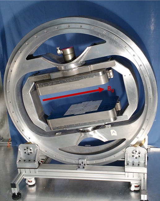
The collagen-rich structures of the knee are prone to damage through acute injury and more chronic “wear and tear”. Osteoarthritis alone is now the 13th most prominent cause of disability adjusted life years, up from 19th in 19901. Angle sensitive MRI can be used to provide more information about orientated collagen in tendons, ligaments, meniscus and cartilage. Being able to visualise these structures clearly and reliably will enable us to devise methods to measure their health, inform clinical decisions and to develop new therapeutic interventions. This research provides a method for use in a novel transverse magnet Figure 1 being developed at Imperial College London2 which will enable in vivo Angle Sensitive MRI imaging.Methods
Angle Sensitive contrast methods have been described by two other groups. One3 used 37 positions along the X and Y axes which excludes any collagen orientated along the Z axis. The second group4 utilised 15 positions; every 30° along X, Y and Z axis which leads to large gaps in the imaging hemisphere. To minimise these gaps, the imaging hemisphere was divided more equally into equidistant points.
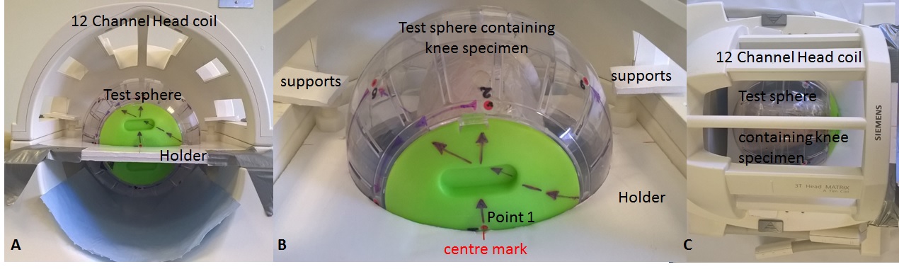
Angle sensitive MRI was applied to a healthy caprine knee model using a Siemens Verio 3T Magnetom Scanner. The caprine knee specimen was mounted in a sphere and placed in a purpose made holder within the 12 channel head coil (Figure 2). The specimen was rotated and scanned in nine equidistant positions so that the knee was orientated at different angles to B0. A 3D 1x1x1 isotropic PD SPACE sequence was optimised using a TR1300ms TE13ms FOV256mm and band width of 434Hz. The PD VAR option was selected which allowed the variable flip angles across the echo train to be optimised for short echo times to allow for a greater Angle Sensitive effect.
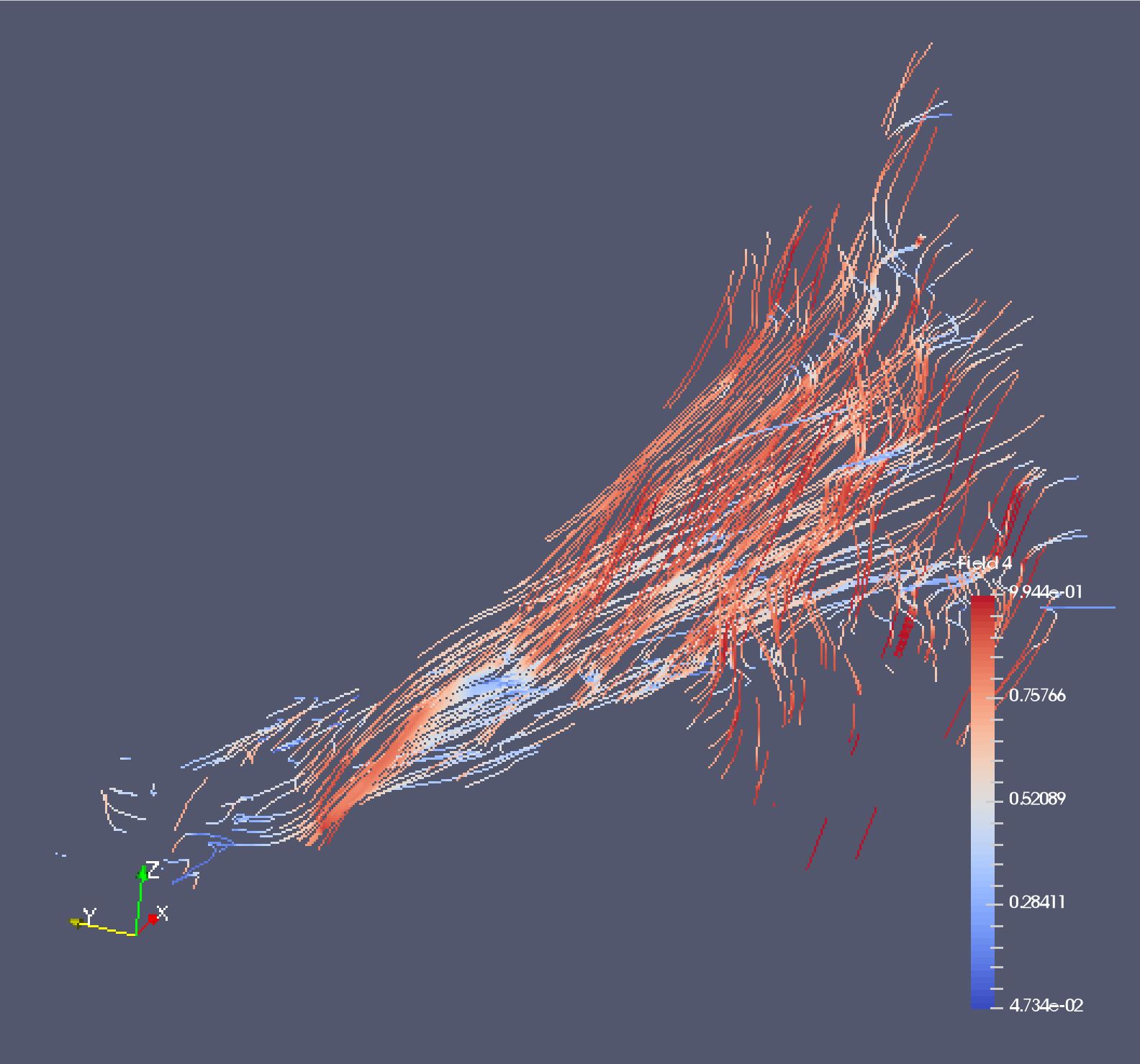
Post processing involved registration of the nine volumes using three fiducial markers that are localised in each differently orientated volume using a template matching method implemented in 3D. The registered volumes were compared by the standard deviation (stdev) of signal intensity over all nine volumes, producing an Angle Sensitive contrast volume (Figure 3). Anatomy of interest was selected from the Angle Sensitive contrast volume and automatically segmented using upper and lower stdev thresholds. This identified voxels containing orientated collagen. Collagen orientation was computed for each voxel using Szeverenyi and Bydder’s4 method producing an orientation vector for each segmented voxel. All post processing steps were conducted using MATLAB5 with in house scripts. A 3-D model of the collagen fibre tracts was produced using ParaView6 5.1.2 32-bit with streamline filter.
Results
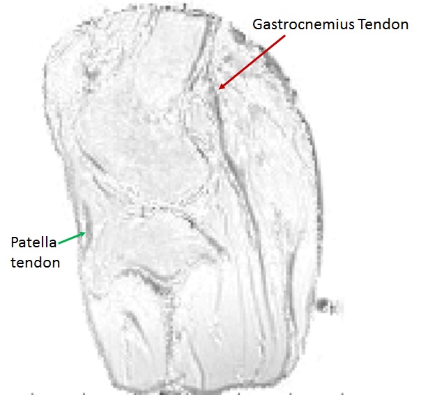
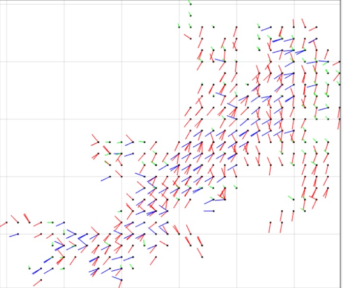
Using nine equidistant positions is a new approach ensuring coverage of the whole test sphere. The number of positions to B0 needed to allow Angle Sensitive contrast is dependent on the image noise: the greater the noise, the more positions are required. The orientation vectors are visualised using the same convention for diffusion tensor imaging (DTI); red indicates the vertical axis, blue indicates the left-right horizontal axis and green indicates the in-out axis. The Anterior Cruciate Ligament (ACL) orientation vectors are shown in Figure 4. Figure 5 demonstrates that it is possible to visualise the anteriomedial and posteriolateral collagen fibre bundles in the ACL.Discussion
This method allows the same accuracy in computing orientation for each collagen voxel. Sphere positioning does not need to be accurate as it is determined in the post processing using the location of the fiducials. Distortion across the imaging volume caused edge effects during registration; a method to correct this is being implemented for each structure individually. The orientation vectors and ParaView6 images of collagen tracts in the ACL appear to represent in vivo structures.Conclusion
The optimal number of positions required for clinical knee Angle Sensitive MRI was determined to ensure a patient could be imaged in the quickest possible time. Our findings have been used to program the rotations of the transverse magnet in the prototype scanner (Figure 1). Improving the design of the prototype scanner and speeding up the post processing steps will allow for immediate Angle Sensitive MRI with collagen tract orientations. Future research will ascertain how Angle Sensitive MRI can be best utilised in clinical practice. It is hoped that a better understanding of collagen orientation will also lead to improved implant design and new therapeutic interventions for conditions such as early osteoarthritis.Acknowledgements
This research was supported by the National Institute for Health Research (NIHR) Invention for Innovation (i4i) under Grant II-LA-1111-20005.
We are grateful to Charing Cross Hospital MRI department and Imaging Committee for the kind use of the Siemens 3T Verio.
References
1 GBD 2015 Mortality and Causes of Death Collaborators. 2016. Global, regional, and national life expectancy, all-cause mortality, and cause-specific mortality for 249 causes of death, 1980–2015: a systematic analysis for the Global Burden of Disease Study 2015. The Lancet, 388:10053. 1459–1544.
2 McGinley, J.V.M., Ristic, M. and Young, I.R. 2016. A permanent MRI magnet for magic angle imaging having its field parallel to the poles. Journal of Magnetic Resonance. 271: 60-67.
3 Seidel, T., Hammer, N., Garnove, N., Schneider, G. and Steinke, H. 2013. An algorithm for the calculation of three-dimensional collagen fiber orientation in ligaments using angle-sensitive MRI. Magnetic resonance in medicine : official journal of the Society of Magnetic Resonance in Medicine / Society of Magnetic Resonance in Medicine, 69: 1595-602.
4 Szeverenyi, N.M. & Bydder, G.M. 2011. Dipolar anisotropy fiber imaging in a goat knee meniscus. Magnetic Resonance in Medicine.65: 463–470.
5 MATLAB and Statistics Toolbox Release 2015a. The MathWorks Inc., Natick, Massachusetts, USA.
6 Ahrens, J., Geveci, B. & Law, C. 2005. ParaView: An End-User Tool for Large Data Visualization, Visualization Handbook, Elsevier, Burlington, Massachusetts, USA.
Figures