0303
Relating external magnetic field changes to head movement using motion and field cameras1Physics and Astronomy, University of Nottingham, Nottingham, United Kingdom
Synopsis
The effect of head movement in high-field MRI is assessed by measuring changes in the spatial pattern of magnetic field perturbation, generated outside the head, using a set of 16 NMR probes fixed into a specially constructed coil mount. Information from the field probes was combined with head position measurements provided by an optical tracking system and quantitative relations between field and position changes were characterised. By relating the field probe and optical tracking measurements, acquired in a training-phase, it was possible to predict head movements based solely on measured magnetic field changes made in subsequent recordings.
Introduction
Head movement is a significant issue in high-field MRI, limiting the achievable spatial resolution. A variety of methods for monitoring head movement, including optical tracking 1 and navigator-based methods 2, have been developed to enable prospective 3 and retrospective correction of motion artefacts 4,5. Here we explore the feasibility of an alternative approach, which involves measuring changes in the spatial pattern of magnetic field perturbation outside the head, resulting from head movement. Field changes were monitored using NMR-based field probes 6, while simultaneously tracking the head position, using an optical system. A model relating head position to field variation is generated from data, recorded during a model-formation-phase. Its ability to predict head movements was then tested on field measurements from separate recordings. This technique therefore allows head position reconstruction based solely on field changes, without any additional setup.Method
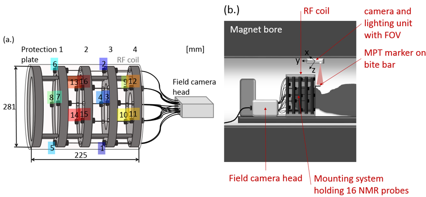
Measurements were made on a 7T Philips Achieva scanner, using a 16-channel clip-on field camera (Skope, Zurich) and a single-camera, Moiré Phase Tracking (MPT) system (Kineticor, Hawaii). A five-ring mount, which held the probes in proximity to the subject’s head was designed to fit inside the volume RF coil (Figure 1a). The changes in the magnetic field at each probe were sampled at 5.7Hz. During the experiments, the Kineticor system tracked the position (sampling frequency: 85Hz) of a single MPT marker attached to a bite-bar that incorporated a dental mould of the subject’s upper teeth (Fig. 1b). Repeated measurements were made on five different subjects in 10 different experimental sessions. In each session, three, 44s-duration recordings were made, during which the subject was cued to carry out two different types of head movement sets. In the first two recordings (M1) and (M2), the subject executed small head shaking movements (yaw), followed by head nodding (pitch), head translation in the foot-head direction and drawing a figure-of-eight with the nose, for successive 11s periods. In the third recording (M3), the subject was asked to make foot movements, which generated small changes in head position. Three of the subjects additionally performed small fixed changes in head orientation (yaw and pitch). The relationship between the spatial pattern of field variation $$$b$$$ and head position $$$\delta$$$, measured via the MPT system, was modelled using a multi-linear approach 7:
$$\delta_l (t) = \alpha_l + b_m(t) \cdot A_{m,l} \quad\quad\quad\quad\quad\quad\quad\quad \text{Eq. (1)}$$
where $$$b_m(t)$$$ and $$$\delta_l(t)$$$ represent the magnetic field change measured at the $$$m$$$th probe, and the estimated change in the $$$l$$$th position co-ordinate, at time point $$$t$$$. $$$A_{m,l}$$$ is the connection matrix and $$$\alpha_l$$$ the intercept estimate, whose coefficients are predicted by fitting to the training data (M2), through inversion of Eq. (1) .
Results
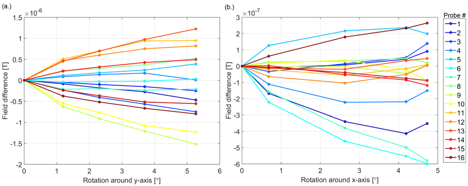
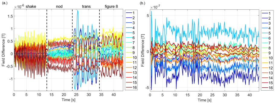
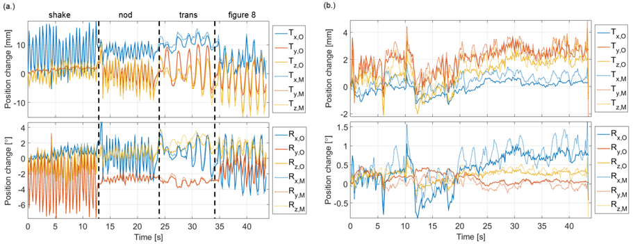
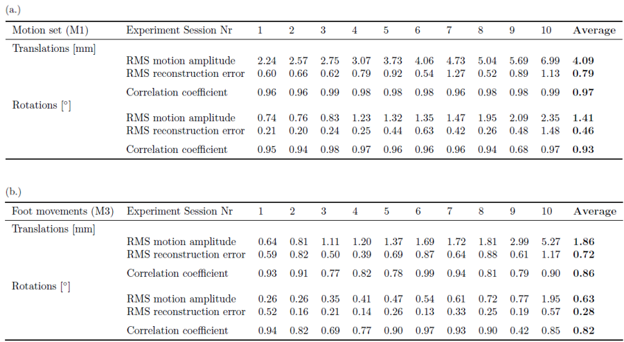
The measured fields vary smoothly with changes in head orientation, and different spatial patterns of field variation are produced by different types of movements (Figures 2 and 3). This is also evident from the correlated variations of field and head position during the M1 and M3 recordings, shown for one subject in Figures 3 and 4 (average correlation coefficients across subjects: translations M1: 0.97; M3: 0.86 and rotations M1: 0.93; M3: 0.82). The average RMS amplitude of the field variation was 0.24μT and 0.13μT for the M1 and M3 measurements, respectively. Figure 4 also shows the translation and rotation parameters estimated from the field measurements at each time-point, using the multi-linear model derived from the separate M2 recording. The measured and estimated position variations are in good agreement for the larger movements in the M1 recording, but there are more significant deviations in the case of the M3 recording, where smaller head movements occurred (results are detailed in Figure 5). The relative errors are generally smaller for larger movements and head translations are more accurately estimated than head rotations (average ratio of error to amplitude: translations M1: 0.21; M3: 0.0.23 and rotations M1: 0.31; M3: 0.51).Discussion
The results demonstrate that measurements of the pattern of spatial field variation, close to the head, provide diagnostic information about head movements. By modelling the field variation, using a simple multi-linear approach, with model parameters calculated from a training data-set, it was possible to estimate the changes in head position from a separate set of field measurements with a reasonable degree of accuracy, with better performance obtained for the larger motions (M1 vs. M3). Alternative modelling approaches, which take account of the non-linear relationship between field variation and head position, may provide improvements in position estimation accuracy, and simultaneous assessment of field changes related to lung expansion in respiration and drift should improve the correction of smaller movements.Acknowledgements
No acknowledgement found.References
1. Zaitsev M, Dold C, et al. Magnetic resonance imaging of freely moving objects: prospective real-time motion correction using an external optical motion tracking system. Neuroimage 2006 Jul; 31(3):1038-50.
2. AJ. Van der Kouwe, et al. Real-time rigid body motion correction and shimming using cloverleaf navigators, Magn Reson Med. 2006 Nov; 56(5):1019-32.
3. J. Maclaren, et al. Prospective Motion Correction in Brain Imaging: A Review, Magn Reson Med. 2013 Mar; 69(3):621-36.
4. Hu X, et al. Retrospective estimation and correction of physiological fluctuation in functional MRI. Magn Reson Med. 1995 Aug; 34(2):201–12.
5. G.H. Glover, et al. Image-based method for retrospective correction of physiological motion effects in fMRI: RETROICOR, Magn Recon Med. 2000 Jul; 44(1):162-67.
6.C.Barmet, et al. Spatiotemporal magnetic field monitoring for MR, Magn Reson Med. 2008 Jul; 60(1):187-97.
7. M. Babayeva, et al. Accuracy and Precision of Head Motion Information in Multi-Channel Free Induction Decay Navigators for Magnetic Resonance Imaging, IEEE Trans Med Imaging 2015 Sep; 34(9):1879-89.
Figures