0300
Active-marker motion detection with real-time field tracking in the laboratory frame1Institute for Biomedical Engineering, ETH Zurich and University of Zurich, Zurich, Switzerland, 2Skope Magnetic Resonance Technologies, Zurich, Switzerland
Synopsis
We introduce a technique to track NMR markers without a prior calibration measurement. This significantly improves the ease of implementation of field probe based prospective motion correction (PMC). We propose to use rigidly mounted NMR field probes in the laboratory frame to perform concurrent field measurements, which are used for real-time tracking of head-mounted field probes. The proposed method achieves very good tracking performance and is demonstrated in-vivo with PMC of high-resolution brain scans.
Introduction
Rigid-body head motion can corrupt MRI scans of the brain and may be addressed by prospective motion correction (PMC). PMC methods track head motion in different ways and update the scan geometry accordingly [1-5]. Specifically, head-mounted NMR markers can be encoded by the scanner’s gradient fields [3]. Recently, methods have been presented to track NMR field probes [6] without scan time prolongation by either superimposing gradient tones [4], or using the gradient waveforms already present in the sequence[7,8]. However, these methods depend on a gradient system calibration which entails two drawbacks. First, it takes additional scan time, possibly requiring to run the whole sequence. A change of sequence parameters may require a new calibration. Second, the calibration is generally limited by system stability. For this reason, the approaches in [6-8] focused on reliably reproducible high signal frequencies. For maximum tracking sensitivity, it would be desirable to use the full waveform spectrum.
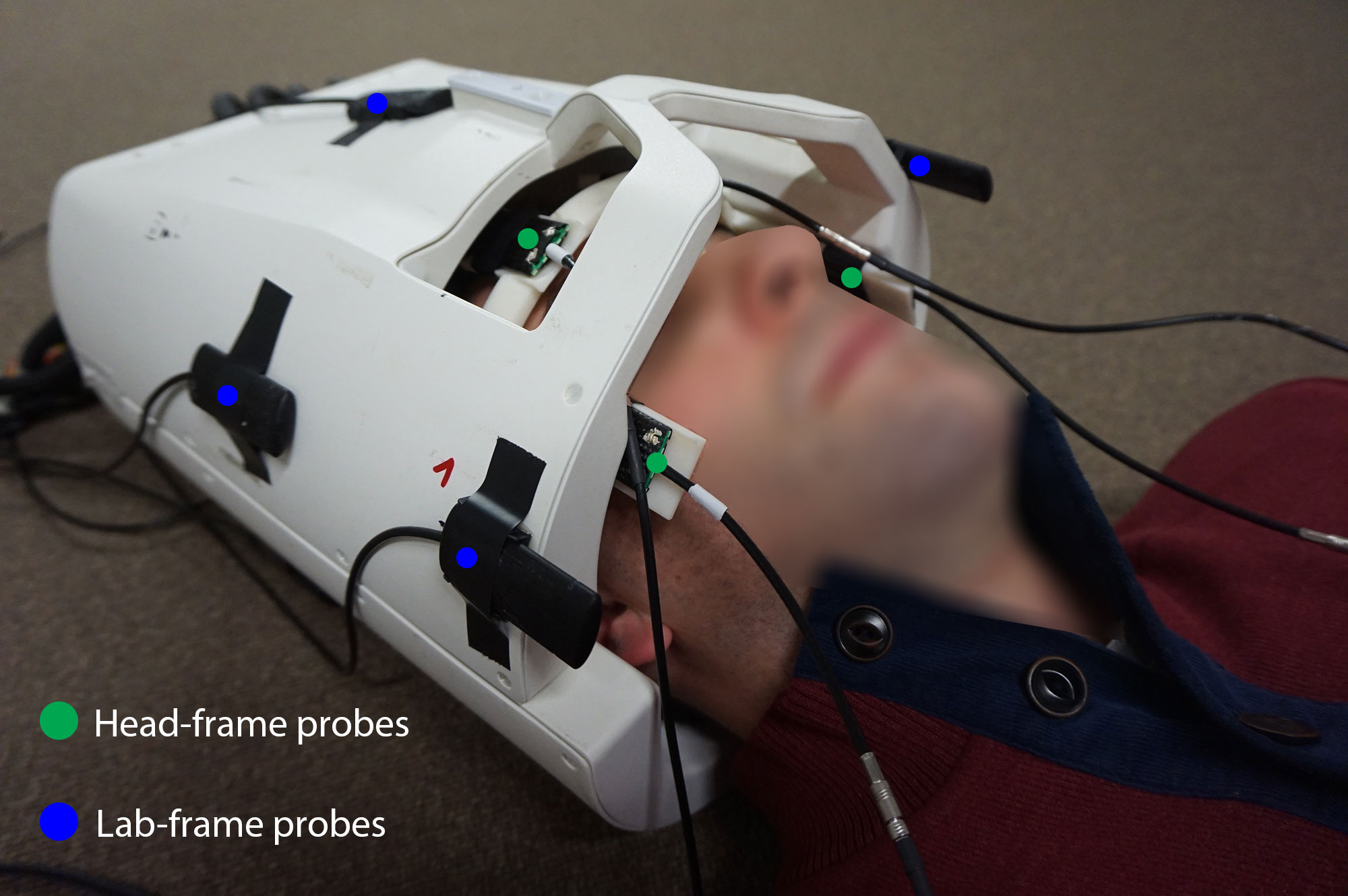
In this work, we overcome these problems by adding field probes in the laboratory frame. The additional probes are rigidly attached to the transmit and receive arrays and perform concurrent field measurements, which serve to compute the positions of the head-mounted probes (Fig.1). This obviates the need for calibration and renders the full waveform spectrum reliable for position tracking. The proposed method is validated in-vivo with PMC of high-resolution brain scans.
Methods
The position of the tracking probes was encoded using gradient tones as suggested in [4], that were superimposed on the spoiling gradients of the sequences. In a first-order model, the time derivative of a probe’s phase accrual reads $$$\frac{1}{\gamma}\frac{d\phi(t)}{dt}=g_0(t)+G(t)r+B_0(r)$$$ with the gyromagnetic ratio $$$\gamma$$$ , the static component $$$B_0(r)$$$ and dynamic field components $$$g_0(t),G(t)$$$. Turning to matrix notation and projecting onto the tones frequencies with the operator $$$F$$$ gives $$$\frac{1}{\gamma}F\dot{\phi}=F(Gr+g_0)$$$, which is solvable for $$$r$$$ if the fields $$$G$$$ and $$$g_0$$$ are known. Instead of calibrating, those are determined during the measurement by a second set of twelve field probes, surrounding the tracking probes and fixed at reference positions. The field computation was done as in field monitoring [9]. Twelve probes yield a very robust first-order field fit, but higher fitting orders may be used. The lab-frame probes were localized by acquiring their FIDs under a static gradient along every axis and computing the frequency shifts [9].
Tracking precision resulted from the standard deviation of estimated rigid-body parameters during a static experiment.
To demonstrate the method’s tracking performance, high-resolution in-vivo scans were performed on a healthy volunteer that was asked to remain still. The scans were repeated with and without PMC. The tracking probes were head-mounted using a 3D-printed frame (Fig.1). All scans were performed on a 7T Philips Achieva system (Philips Healthcare) with a 32-channel receive array (Nova Medical). The probes (head-frame probes T1=1.5ms, lab-frame probes T1=86ms) were run with a dedicated acquisition system [10]. Sequences included a T2*-weighted gradient echo (voxel-size=0.3x0.3x2 mm³, TR/TE/flip-angle= 720ms/25ms/45°, 15 slices, duration=9:13min, flow compensation, tones: duration=1ms, amplitude=7mT/m, frequencies=(2;3;4)kHz) and a 3D T1-weighted MPRAGE sequence (voxel-size=0.6x0.6x1.4mm³, duration=13:26min, TR/TE/flip-angle=6.8ms/3.1ms/7°, partial Fourier=0.95 (Y-direction), averages=2, FOV=220x220x111mm³, tones: duration=0.75ms, amplitude=7.7mT/m, frequencies=(1.34;2.67;4)kHz).
Results
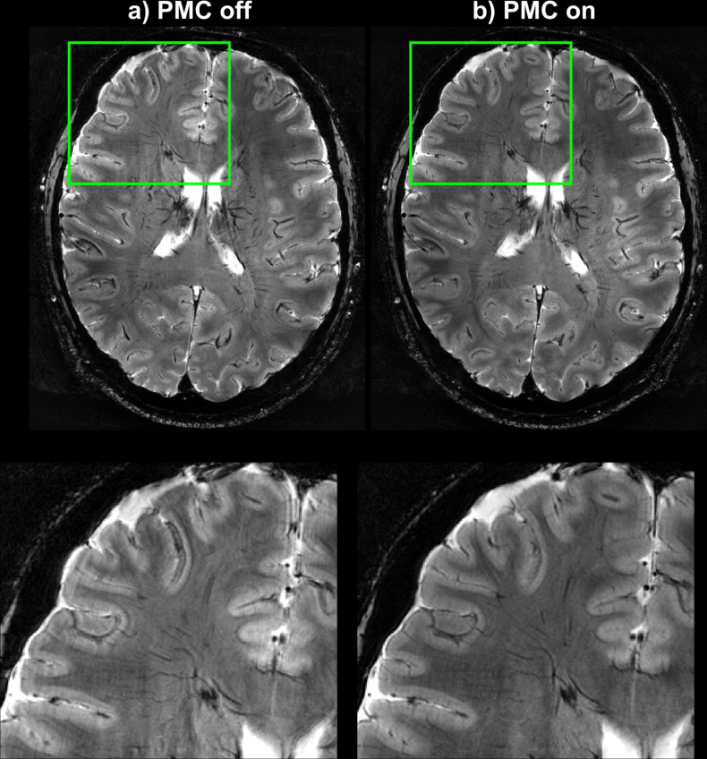
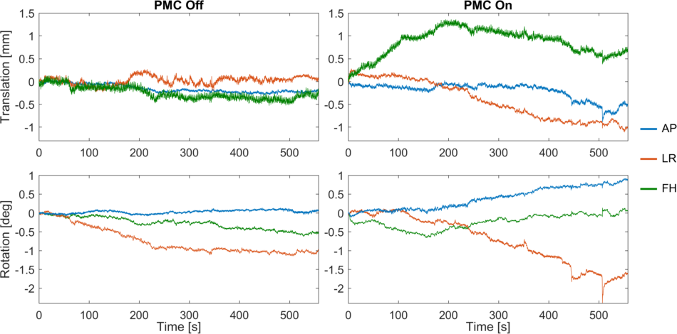
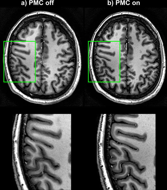
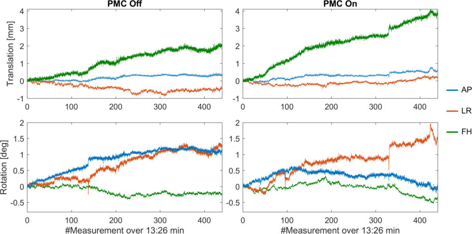
The tracking precision along each translation and rotation axis was <12µm and <0.007° for the T2*-case and for the MPRAGE-case <24µm and <0.02°, respectively. Fig.2 shows images from the T2*-weighted scan and the zoomed view provides clear evidence of better image quality in the corrected case, despite significantly more subject motion during that scan (Fig.3). The clear depiction of little veins and vessels in the corrected case testifies to high tracking precision and accuracy. In the uncorrected image, visible artefacts were caused by subtle involuntary head motion. In the MPRAGE-case (Fig.4), the corrected image exhibits visibly improved image quality with clear contours, while they are blurred out in the uncorrected image. Fig.5 displays head motion parameters during both scans.Discussion and Conclusion
The addition of field probes in the lab-frame allowed to track head-mounted field probes with high precision and without the need for calibration. The method’s capability to perform PMC was demonstrated in-vivo with high-resolution brain scans. The proposed method greatly streamlines the workflow of field probe based PMC and guarantees very reliable probe tracking due to real-time field measurements. The suggested method can be applied with other techniques for field probe localization, e.g. [8]. Moreover, a higher-order field model can readily be adopted, which may further increase tracking accuracy. The presented method lends itself to integration with field monitoring. The calibration-free approach to field probe based PMC presented in this work opens up the possibility to conveniently perform PMC experiments with very long MRI scans.Acknowledgements
No acknowledgement found.References
[1] Maclaren et al, MRM 69(3):621-36 (2013) [2] Zaitsev et al, Neuroimage 31:1038–1050 (2006) [3] Ooi et al, MRM 62: 943–954 (2009) [4] Haeberlin et al, MRM 74: 647–660 (2015) [5] van der Kouwe et al, MRM 56: 1019–1032 (2006) [6] De Zanche et al, MRM 60: 176–186 (2008) [7] Haeberlin et al, Procs. ISMRM 2014, #0883 [8] Aranovitch et al, Procs, ISMRM 2016 #0101 [9] Barmet et al, MRM 60:187-197 (2008) [10] Dietrich et al, MRM, DOI:10.1002/mrm.25770 (2015)Figures