0150
Saccular intracranial aneurysm wall permeability and shear stress distribution: a further insight into rupture pathogenesis1Center for Biomedical Imaging Research, Department of Biomedical Engineering, School of Medicine, Tsinghua University, Beijing, People's Republic of China, 2Department of Interventional Neuroradiology, Beijing Neurosurgical Institute and Beijing Tiantan Hospital, Capital Medical University, Beijing, People's Republic of China, 3Department of Radiology, University of Washington, Seattle, WA, United States
Synopsis
The purpose of this study is to explore the relationship between aneurysm wall permeability and the hemodynamic conditions of intracranial aneurysm (IA). The results showed that hot spot of IA wall permeability was spatially related with significantly lower wall shear stress magnitude and higher oscillatory shear index, which suggests the pathology of IA might be an interaction of both factors, and IA wall permeability could be a potential method for IA rupture risk assessment.
Introduction
Aneurysmal subarachnoid hemorrhage (SAH) is a leading cause of stroke disability and death in young patients, with an estimated initial mortality rate of 50% and up to 50% morbidity in survivors [1]. However, its pathogenesis in vivo remains unclear [2]. Reported as the most frequent cause of non-traumatic SAH [3], intracranial aneurysm (IA) is of great interest to researchers. Previous researches suggested many possible indicators of IA progression or rupture, such as the inflammation [4] and hemodynamic conditions [3, 5]. In recent studies [6, 7], researchers found that pharmacokinetic analysis of the IA DCE-MR images, which may quantify the IA wall permeability, may be an imaging biomarker associated with IA progression [6] and rupture [7]. However, its relationship with hemodynamic conditions remains unclear. In this study, we aimed to explore the relationship between wall permeability and the hemodynamic conditions of IA.Method
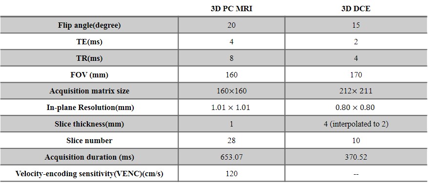
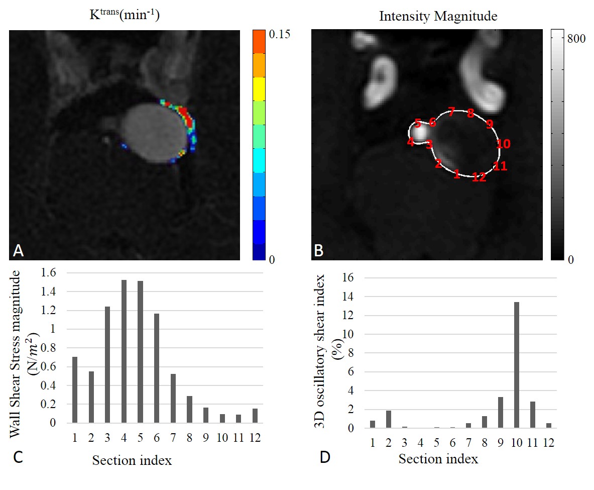
After written informed consent obtained, 13 patients (4 males, mean$$$\pm$$$SD age: 51.76$$$\pm$$$16.53 years) with unruptured saccular cerebral aneurysms IA detected by proceeding CTA examination were recruited. MR imaging: All patients were scanned on a 3.0T whole-body MR scanner (Achieva TX, Philips, Best, The Netherlands) with a 32-channel head coil. The MRI protocol included: 3D time-of-flight sequence for subsequent scans localization, 3D CINE(time-resolved) phase-contrast (PC) MRI and 3D DCE-MRI. 3D CINE PC MRI, which is also called 4D flow, took a 3D radiofrequency-spoiled gradient-echo sequence to measure all 3 blood flow velocity components with a 3D volume covering the IA. Additionally, prospective ECG gating and interleaved 3-directional velocity encoding could offer time-resolved magnitude and velocity data(temporal resolution 46.15-61.22 ms) through the cardiac cycle [8]. DCE MR images of the targeted IA were acquired by a 3D T1-weighted spoiled gradient echo sequence with 8.8 s interval for 10 slices and a total acquisition time of 6 mins. A bolus of 0.1 mmol/kg Gd-DTPA (Magnevist; Bayer Healthcare) was injected during the third dynamic at a rate of 1.5 mL/s. The further parameters of 3D CINE PC MRI and DCE MRI were shown in Table 1. Image analysis: For DCE-MRI, the extended Kety/Tofts model [9] was used to generate the transfer constant ($$$k^{trans}$$$) map. A DCE-ROI covering the highest $$$k^{trans}$$$ region outside but adjacent to the IA wall across all the slices was placed by one neuroradiologist blinded to patient information for each case, after pixels with blood signal contamination ($$$v_p$$$> 0.5) excluded [6]. For 4D flow data, wall shear stress (WSS) magnitude and 3D oscillatory shear index (OSI) were calculated with a validated method [10, 11]. Since we only choose one slice from DCE images for each case in analysis, the corresponding image plane were found from 4D flow images and were analyzed.The circumference of the IA in the selected slice were split to 12 sections for each case, and the WSS magnitude and 3D OSI were calculated for each section. These sections could be classified into 2 groups: group 1, sections correspond (adjacent) to the DCE-ROI with high $$$k^{trans}$$$ values, reflecting the hot spot of IA wall permeability; group 2, other sections without $$$k^{trans}$$$ hot spot. Statistical analysis: To investigate the relationship of the hot spot of IA wall permeability ($$$k^{trans}$$$) and the hemodynamic conditions inside IA, independent-sample T test was performed to compare the WSS and OSI between two groups.Results
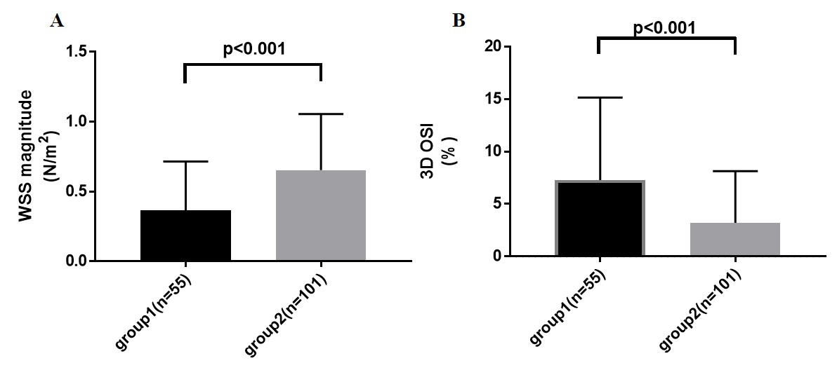
Totally 156 sections from 13 patients were classified into 2 groups: 55 sections in group 1, while 101 sections in group 2. Fig 1 shows a typical case of registered 4D flow image and excessive $$$k^{trans}$$$ values distribution, lower WSS and higher OSI can be seen for the sections near the IA wall permeability ($$$k^{trans}$$$) hot spot in this case. Overall, sections in groups 1 have significantly lower WSS magnitude than group 2 (0.367$$$\pm$$$0.047 vs. 0.654$$$\pm$$$0.040 N/$$$m^2$$$, p<0.001, Fig 2A). Also, the 3D OSI of sections in group 1 were significantly higher than group 2 (7.275$$$\pm$$$1.062 vs. 3.200$$$\pm$$$0.489 %, p<0.001, Fig 2B).Discussion and Conclusion
In this study, high $$$k^{trans}$$$ region outside but adjacent to the IA wall, which should reflects the hot spot of IA wall permeability [6, 7], was found spatially related with lower WSS magnitude and higher 3D OSI. Previous investigation had found that low WSS was associated with IA rupture area [3]. Our results further suggested that the pathogenesis of IA rupture might be an interaction of IA wall permeability and abnormal hemodynamic conditions. Thus, IA wall permeability could be a potential method for IA rupture risk assessment.Acknowledgements
No acknowledgement found.References
[1] Lazzaro, M.A. et al., The role of circle of Willis anomalies in cerebral aneurysm rupture, J. Neurointerv. Surg. 2012, 4: 22–26.
[2] Miyamoto, T. et al., Site-specific elevation of interleukin-1β and matrix metalloproteinase-9 in the Willis circle by hemodynamic changes is associated with rupture in a novel rat cerebral aneurysm model, J. Cereb. Blood Flow Metab. . 2016,.
[3] Frösen, J. et al., Saccular intracranial aneurysm: Pathology and mechanisms, Acta Neuropathol. 2012, 123: 773–786.
[4] Chalouhi, N. et al., Biology of intracranial aneurysms: role of inflammation, J. Cereb. Blood Flow Metab. 2012, 32: 1659–1676. [5] Lu, G. et al., Influence of hemodynamic factors on rupture of intracranial aneurysms: Patient-specific 3D mirror aneurysms model computational fluid dynamics simulation, Am. J. Neuroradiol. 2011, 32: 1255–1261.
[6] Vakil, P. et al., Quantifying Intracranial Aneurysm Wall Permeability for Risk Assessment Using Dynamic Contrast-Enhanced MRI: A Pilot Study, Ajnr. 2015, 36: 953–959.
[7] Qi, H. et al., Intracranial aneurysm wall permeability: a potential risk predictor for rupture, in: Int. Soc. Magn. Reson. Med., 2016.
[8] Wetzel, S. et al., In vivo assessment and visualization of intracranial arterial hemodynamics with flow-sensitized 4D MR imaging at 3T, Am. J. Neuroradiol. 2007, 28: 433–438.
[9] Tofts, P.S., Modeling tracer kinetics in dynamic Gd-DTPA MR imaging, J. Magn. Reson. Imaging. 1997, 7: 91–101.
[10] Stalder, A.F. et al., Quantitative 2D and 3D phase contrast MRI: Optimized analysis of blood flow and vessel wall parameters, Magn. Reson. Med. 2008, 60: 1218–1231.
[11] Meckel, S. et al., In vivo visualization and analysis of 3-D hemodynamics in cerebral aneurysms with flow-sensitized 4-D MR imaging at 3 T, Neuroradiology. 2008, 50: 473–484.
Figures