0133
Mitigation of Spiral Undersampling Artifacts in Magnetic Resonance Fingerprinting (MRF) by Adapted Interleave Reordering1Application Development, Siemens Healthcare, Erlangen, Germany, 2Biomedical Engineering, University of Virginia, Charlottesville, VA, United States
Synopsis
In MRF fast spiral scanning is done with variable FA/TR using a highly – up to 48-fold – undersampled trajectory. Spatial undersampling artifacts are mitigated by the MRF dictionary-matching process for the resulting quantitative T1/T2 maps. In this study, we demonstrate how undersampling artifacts can bias MRF results and present strategies to minimize them by spiral-interleave reordering adapted to the specific MRF encoding scheme. An experimental procedure is developed to test for a potential spatial bias in a specific spiral and MRF encoding scheme. The sources of spatial variances are mitigated with appropriate distribution of undersampling artifacts over the temporal MRF encoding.
Purpose
In MR Fingerprinting (MRF), fast spiral scanning is done with variable FA/TR using a dual-density, highly – up to 24-48-fold - undersampled trajectory1,2. Spatial undersampling artifacts are mitigated by the MRF dictionary matching process for the resulting quantitative T1/T2 maps2. In this study, we investigated how the order of spiral interleaves in the acquisition can bias the MRF matching. An experimental procedure was developed to test for a potential spatial bias in a specific spiral and MRF encoding scheme. Thus, the interleave reordering (ILR) scheme can be adapted and optimized accordingly.
Methods
Experiments were performed on a head-shaped gel phantom and healthy subjects on a MAGNETOM Aera 1.5T and Skyra 3T (Siemens Healthcare, Erlangen, Germany). 2D MRF-FISP2 data were acquired using a prototype sequence with the following parameters: FOV 300 mm, resolution 1.17x1.17x5 mm3, variable TR (12-15 ms), FA (5-75°), Rep 3000. Spiral reconstruction and MRF matching was done inline. 48 spiral interleaves with rotation-angle increments of 360°/48=7.5° were designed with dual radial density (2,1). Images were reconstructed per repetition from single interleaves (with different rotation angles) and thus revealed strong undersampling artifacts, which were mitigated in the MRF matching process.
Experiments were performed with different interleave reordering (ILR) and different interleave offset (IL-Offset) for the subsequent repetitions. The reference ILR scheme was “ascending” (“STEP-1”); different ILR increments “STEP-x” (x = 1…15) were tested as well as “descending” (STEP-[-1]), “alternating” (STEP-24), and “random”. The starting interleave was defined by the IL-Offset. The ILR vector was constructed by a modulo-48 and shift-[+1]-IL-Offset operation until all 48 interleaves were filled. For example:
ILR=STEP-1, IL-Offset=24: [25,26,27,…,48,1,2,…23,24]
ILR=STEP-14, IL-Offset=0: [1,15,29,43,…,35,2,16,30,44,…,36]
The signal variation in a series of ILR STEP-1 experiments with different IL-Offsets [0,1,2,…,47]/48*360° was analyzed voxelwise. A “phase” was calculated from the maximum IL-Offset position; a “magnitude” by re-sorting circularly to align the signal courses for different voxels.
“Shading” maps were calculated by the difference of IL-Offset 0 and 180° maps divided by 2 and normalized to the mean T1/T2 value.
Results and Discussion
Series of T1/T2 maps (Figure 1A,1B) in a head-shaped gel phantom are shown with different IL-Offsets. For both T1 and T2, a rotating signal variation (“shading”) is visible. Signal variation was strongest for T1 at 3T and reduced for T2 and 1.5T, respectively.
Vastly different spatial variation was found for some ILR schemes (e.g. “ascending”, “descending”, “alternating”), while being reduced or nearly absent for “random” and STEP-14 (Figure 1C). A good experimental test to assess shading was to acquire a pair of antisymmetric IL-Offset modes like 0°/180° and calculate shading maps, which also worked for human data with varying T1/T2 for each voxel.
Results of different ILR schemes and four IL-Offsets (0,90,180,270°) are shown as mean/stdev over the whole object (Figure 2). Strongest variance was found for STEP-1, STEP-8, and STEP-12. ILR with overall minimal (spatial) variation were STEP-x=4,5,11,13,14 –optimal schemes were STEP-11 and STEP-14. Similar results were obtained for the different object shapes in axial, sagittal and coronal orientation.
The signal variation of the “ascending” mode was analyzed magnitude/phase-like, which revealed a smooth rotating phase over the object (Figure 3). The signal course was cosine-type, with a modulation of ±20% of the target T1 value. Antisymmetric and orthogonal modes were shifted towards larger indices and found to be at 30/48 (225°) and 14-38/48 (105°, 285°), respectively. Further theoretical modeling and simulations are presented elsewhere3. Optimizations of the ILR scheme may depend on the specific spiral design and sampling density as well as the chosen FA/TR MRF-encoding.
Similar results were found in the human brain at 1.5T and 3T. Rotating shading with different IL-Offset was mitigated with ILR STEP-14, for both T1 and T2 maps (Figure 4). A shading map was calculated from ILR STEP-1 with IL-Offset 0°/180°. T1 variation was ±20% (±12% for T2), similar to the phantom. In contrast, ILR STEP-14 had only a minimal variation around zero (Figure 4C).
Excellent intrasubject repeatability was found for T1/T2 maps in the human brain with IL-Offset 0°/180° and different orientations, when using the new ILR scheme (Figure 5). For example, T1 in an ROI in frontal white matter (left/right hemisphere) was (876±42) / (872±42) and (876±45) / (871±48) ms (repeated acquisitions with IL-Offset 0°/180°).
Conclusion
Subsampling in MRF is essential for efficient scanning, but related artifacts may impact results unless carefully treated. Bias in quantitative MRF maps can be minimized by spiral interleave reordering adapted to the specific spiral and MRF encoding scheme. The sources of spatial variances are mitigated with appropriate distribution of undersampling artifacts over the temporal MRF encoding.
Acknowledgements
We gratefully thank Prof. Mark Griswold and his group and collaborators at Case Western Reserve University, Cleveland, OH for support and for many intensive discussions.
References
-
Ma D, Gulani V, Seiberlich N, Liu K, Sunshine JL, Duerk JL, Griswold MA. Magnetic resonance fingerprinting.Nature. 2013 Mar 14;495(7440):187-92. doi: 10.1038/nature11971.
-
Jiang Y, Ma D, Seiberlich N, Gulani V, Griswold MA. MR fingerprinting using fast imaging with steady state precession (FISP) with spiral readout. Magn Reson Med. 2015 Dec;74(6):1621-31. doi: 10.1002/mrm.25559. Epub 2014 Dec 9.
-
Körzdörfer G et al., Spatial biases in Magnetic Resonance Fingerprinting parameter maps arising from undersampling patterns, Proceedings ISMRM 2017, submitted.
Figures
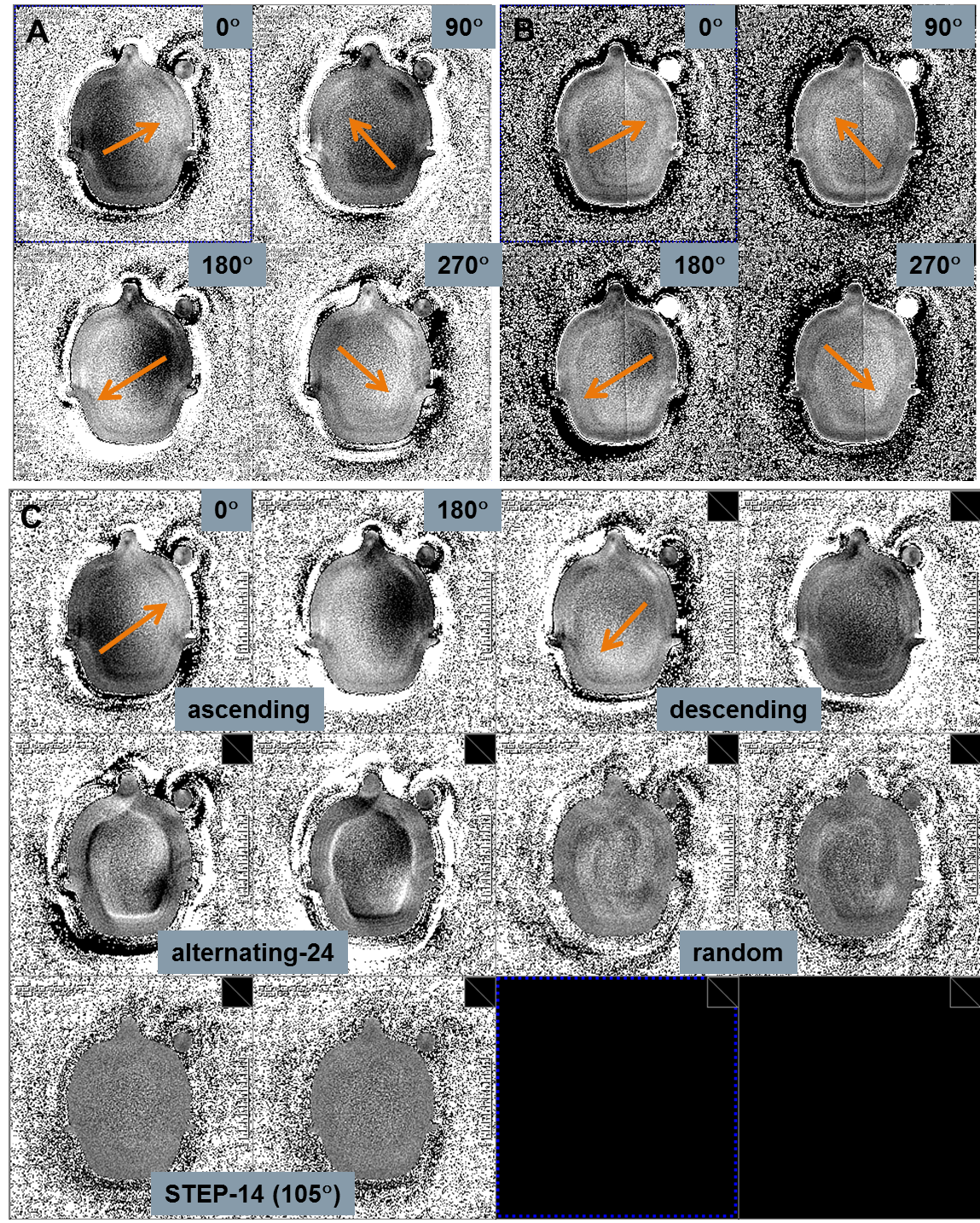
Series of T1 maps (A) and T2
maps (B) in a head-shaped gel
phantom at 1.5T. Interleave-Reordering is ascending (STEP-1) with
Interleave-Offset (0,90,180,270°). (C) Different ILR with IL-Offset 0,180°. In contrast to various ILR
schemes, ILR STEP-14 only has a minimal spatial variation and is invariant to a
different IL-Offset.
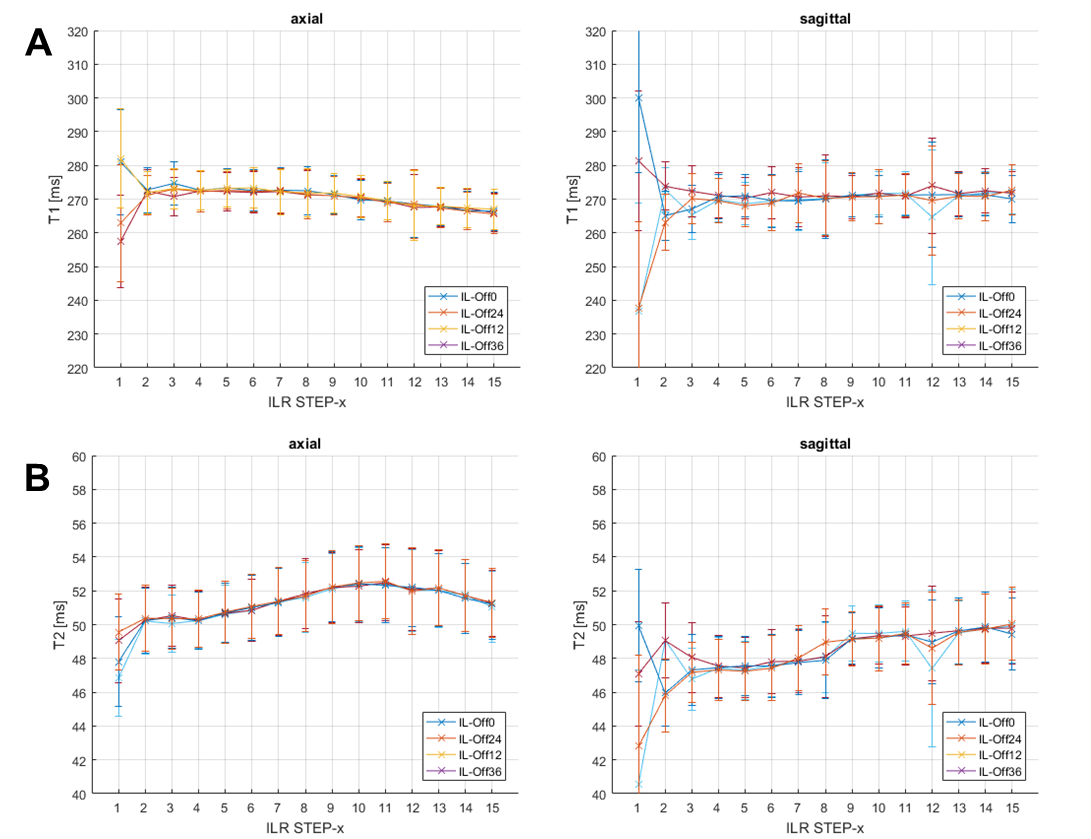
Evaluation of different ILR STEP-x (x = 1...15) and IL-Offsets (0,90,180,270°) of T1 maps (A) and T2 maps (B) in a head-shaped gel phantom at 3T. ILR with overall minimal spatial variation, i.e. stdev, are STEP-11, STEP-13, and STEP-14.
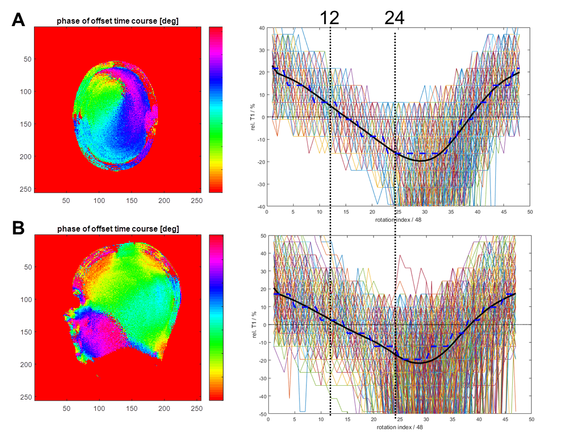
Evaluation of axial (A) and sagittal T1 maps (B) in a head-shaped gel phantom at 3T using ILR “ascending” and IL-Offset [0,1,2,…,47]/48*360°. Signal variation with IL-Offset was analyzed voxelwise: phase calculated from maximum and circularly re-sorted to align signal courses. A cosine-type variation was found; however, zero crossing and signal minima were not at index 12 and 24, but shifted to larger indices.
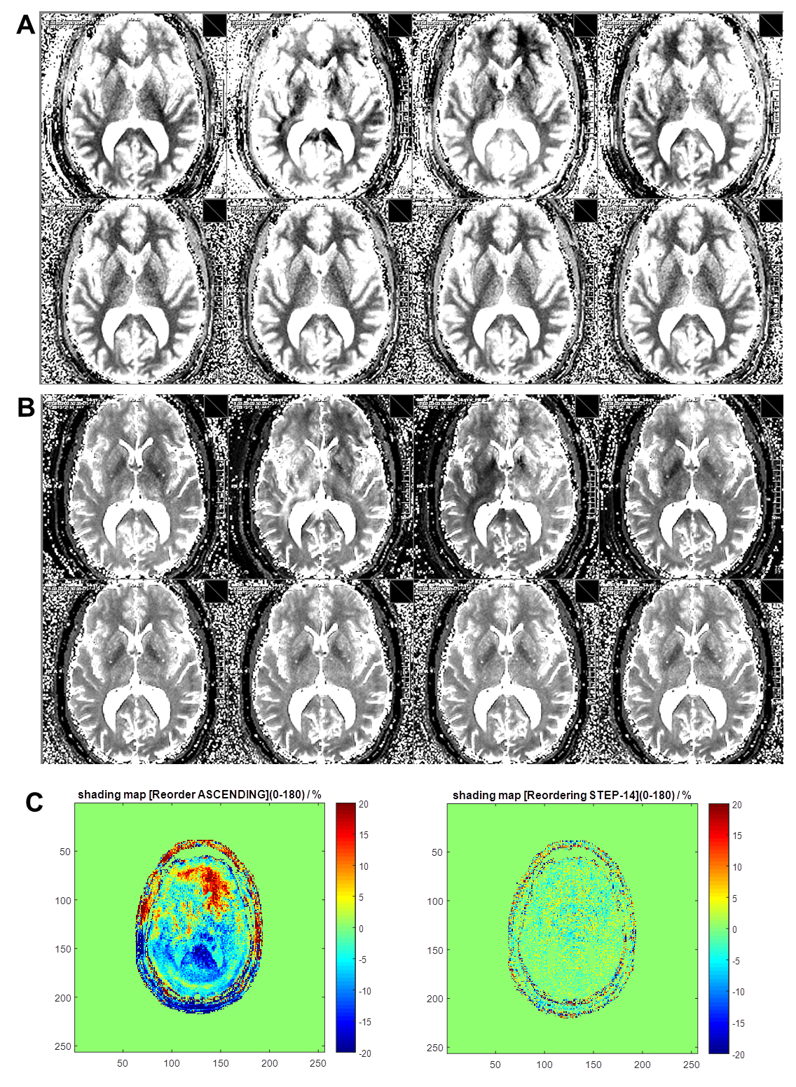
Series of T1 maps (A) and T2
maps (B) in the human brain at 3T.
IL-Reordering is ascending (top) and STEP-14 (bottom) with IL-Offset
(0,90,180,270°). (C) Shading maps calculated from
IL-Offset 0 and 180°. ILR mode
ascending shows T1 variations of ±20%
(left), ILR STEP-14 only has a minimal variation around zero (right).
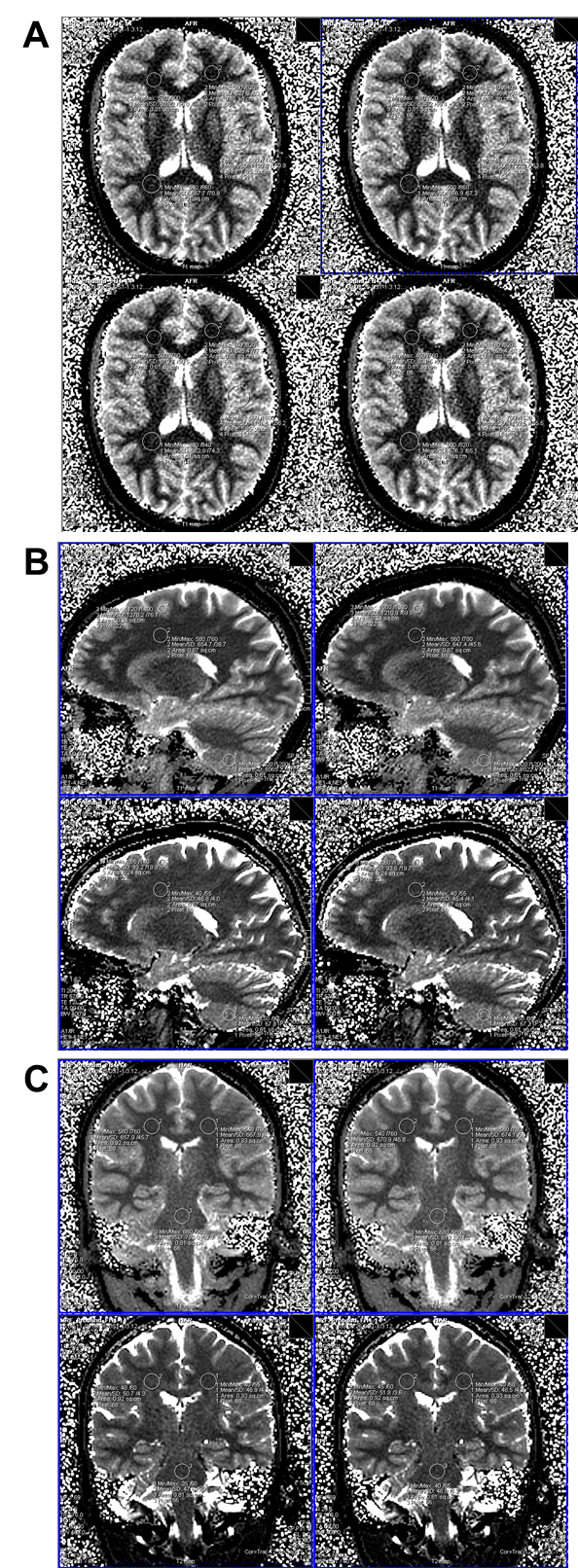
T1 maps (top) and T2 maps (bottom) of the human brain at 1.5T (ILR STEP-14, IL-Offset 0° and 180°, left/right) at different orientations: axial (A), sagittal (B) and coronal (C).