0108
Detecting orientation selective deep brain stimulation using BOLD fMRI1Center for Magnetic Resonance Research, University of Minnesota, Minneapolis, MN, United States, 2Department of Biomedical Engineering, University of Minnesota, Minneapolis, MN, United States, 3A. I. Virtanen Institute for Molecular Sciences, University of Eastern Finland, Kuopio, Finland, 4Department of Neurosurgery, University of Minnesota, Minneapolis, MN, United States
Synopsis
Spatial selectivity is of high importance for Deep Brain Stimulation (DBS). Here we used BOLD fMRI to demonstrate for the first time that axon-orientation selective stimulation can be achieved in the rat’s corpus callosum by steering the stimulus phase of the independently driven channels in a tripolar DBS electrode. Pronounced angular dependence of the BOLD fMRI on the orientation of electric field gradient was detected. As expected based on simulations, the maximal (or minimal) BOLD response was observed when the induced dipole field was parallel (or perpendicular) to the axonal tract, respectively.
Purpose
Target selection is critical for deep brain stimulation (DBS) as it allows to minimize adverse side effects and to ensure optimal response to the DBS therapy. So far, spatial selectivity has been achieved by steering electric fields when stimulating only a selected side of an electrode with multiple channels1-3. Here, we used BOLD fMRI to demonstrate that it is possible to stimulate axons selectively based on their orientation using three independently driven channels with amplitudes chosen based on phase offset sinusoids.Methods
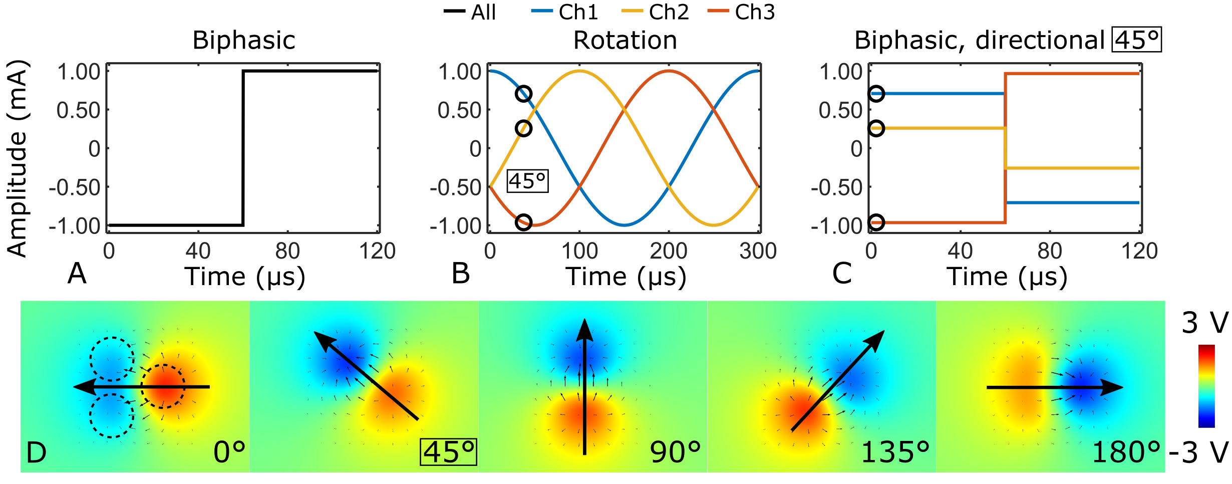
The efficacy of inducing an action potential in an axon depends on the spatial derivative of the stimulating E-field parallel to the axon4. With a three-channel electrode, control of the orientation of the E-field can be achieved by selecting the stimulation current amplitudes based on sinusoidal functions with 120° phase offsets (Figure 1). This induces an electric dipole field with a primary axis that can be rotated freely on a plane. Three-channel (200 µm diameter) tungsten electrodes were implanted in the rat corpus callosum (n = 12), and the stimulation angle was adjusted in 30° steps for a total of 13 fMRI acquisitions. The stimulation paradigm consisted of 60 s of rest, 18 s of stimulation, repeated twice and ending in rest. Imaging was conducted at 9.4 T using SE-EPI with the following parameters: TR = 1.5 s, two shots, TE = 35 ms, resolution 0.4 x 0.4 x 1.0 mm3 and 11 slices. DBS parameters were: square, biphasic charge balanced pulses, length 60 µs, repetition rate 20 Hz and amplitude 0.9 – 1.2 mA. fMRI data was processed in SPM and time series were averaged over the animals assuming that stimulation angle with strongest BOLD response corresponds to 0° or parallel to axons. To further support our fMRI results, axons in different orientations relative to the dipole field were simulated using COMSOL and NEURON simulation environments.Results
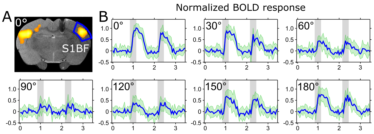
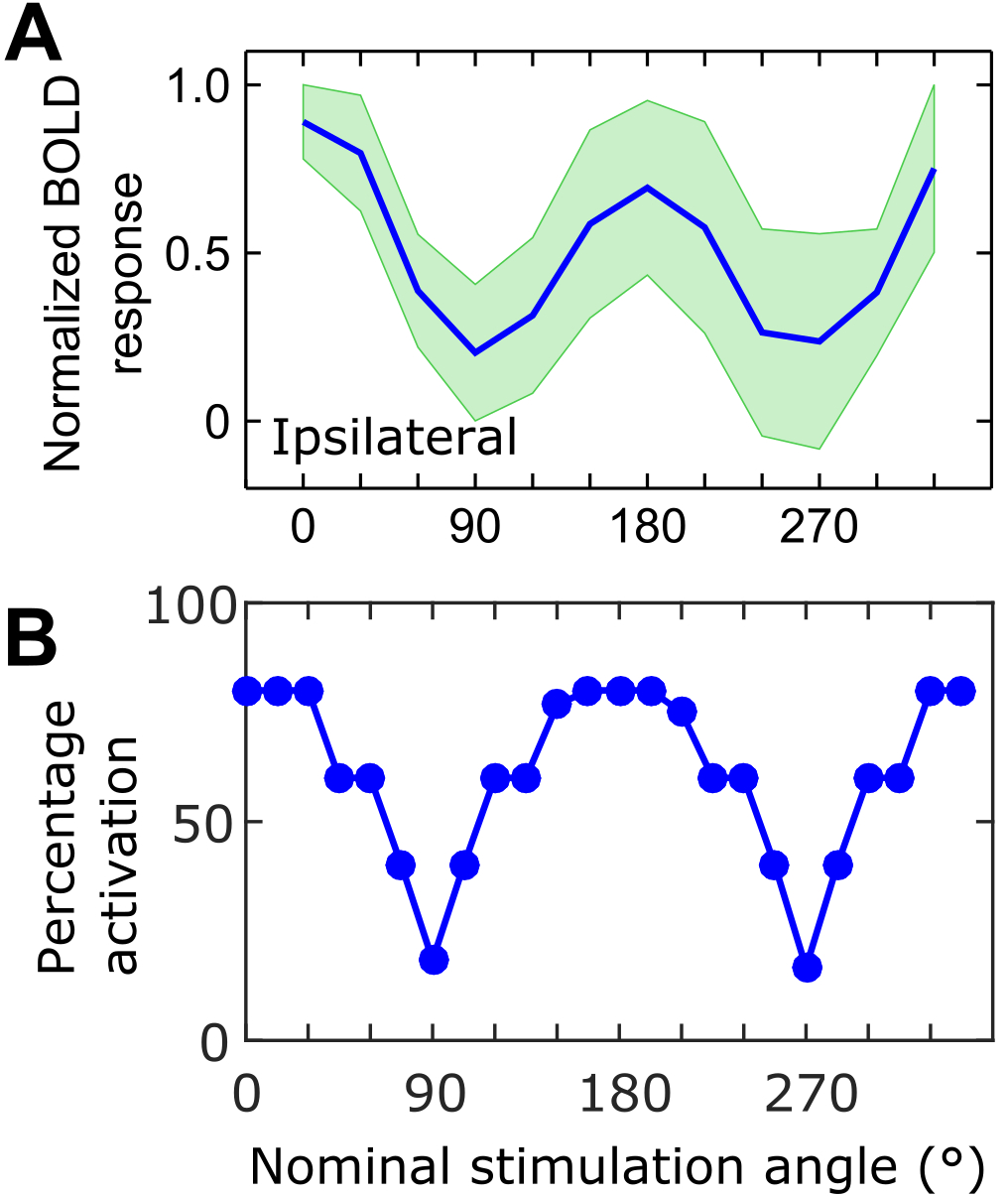
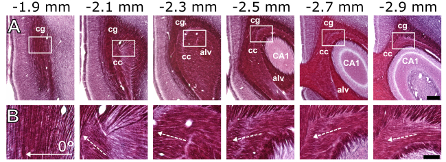
Maximal and minimal BOLD responses were observed in the primary somatosensory cortex (S1) when the dipole field gradient was parallel and perpendicular to the fibers of the corpus callosum, respectively (Figure 2). Having the dipole field at orientation of 0° (cathode towards the ipsilateral side) or at 180° compared to the nominal direction of the axons resulted in nearly the same group averaged peak response with no statistically significant difference (Figure 3A). The stimulation angles with maximum and minimum response of the simulated axons matched with the experimental observations (Figure 3B). Based on fitting a Gaussian to the peak BOLD response curve (Figure 3A) without normalization of the angles, the peak activation had an offset of 16° ± 17° from nominal zero angle direction. This observation was attributed to the directionality of the fibers of the corpus callosum that in reality is not necessarily in the anterior-posterior direction as seen in myelin stained sections (Figure 4).Discussion
In this work, a new strategy for orientation-selective paradigms for DBS was developed and whole brain activation response was monitored using fMRI. The method aims at increasing precision of targeted activation beyond currently employed shaping and steering approaches1-3. Here, this was achieved using variable sets of amplitudes and a multichannel electrode configuration, which enabled control of the orientation the spatial gradient of the electric field. The activation detected in rat’s brain area S1 exhibited dramatic dependence on the reorientation of electric field gradient generated from the tripolar electrode implanted in the corpus callosum. Our computational analysis indicated a pronounced angular dependence of the excitability of axons with respect to the orientation of the stimulating electric field, which was in agreement with the experimental findings. The present study demonstrates that an electrode design with multiple and independently driven channels inherently provides large flexibility in orienting the electric field in space irrespective of the orientation of electrode implantation.Conclusion
There is a critical need to improve DBS technology beyond currently available stimulation steering and shaping approaches. fMRI provides whole brain coverage for detection of stimulation response which is extremely valuable when developing novel stimulation paradigms for DBS. Our results demonstrate excellent selectivity of stimulating axons with different orientations of electric field gradient. Further improvements can be achieved by implementing a more refined electrode design with multiple channels distributed in three-dimensions, in combination with more advanced amplitude and phase modulated paradigms.Acknowledgements
This work was supported by the following sources: NIH grants: P41-EB015894, P30-NS057091, R01-NS081118, R01-NS094206; UEF-Brain Pool; Michael J Fox Foundation; WM KECK Foundation; Fulbright-Saastamoinen Foundation Grant in Health and Environmental Science to SM; MnDRIVE post-doctoral fellowship to LJL; and NSF IGERT fellowship (DGE-1069104) to JPS; Academy of Finland.This project has received funding from the European Union's Horizon 2020 research and innovation programme under the Marie Sklodowska-Curie grant, agreement No 691110 (MICROBRADAM)References
1. Martens, H. C., Toader, E., Decre, M. M. et al. Spatial steering of deep brain stimulation volumes using a novel lead design. Clin Neurophysiol. 2011;122(3): 558-566.
2. Connolly, A. T., Vetter, R. J., Hetke, J. F. et al. A Novel Lead Design for Modulation and Sensing of Deep Brain Structures. IEEE Trans Biomed Eng. 2016;63(1): 148-157.
3. van Dijk, K. J., Verhagen, R., Chaturvedi, A. et al. A novel lead design enables selective deep brain stimulation of neural populations in the subthalamic region. J Neural Eng. 2015;12(4): 046003.
4. Rattay, F. Analysis of models for extracellular fiber stimulation. IEEE Trans Biomed Eng. 1989;36(7): 676-682.
5. Paxinos, G. and Watson, C. The rat brain atlas in stereotaxic coordinates. San Diego: Academic. 1998
Figures