0014
Acousto-optic Based Active MRI Marker for Interventional MRI Devices1G.W. Woodruff School of Mechanical Engineering, Georgia Institute of Technology, Atlanta, GA, United States, 2Institute of Biomedical Engineering, Bogazici University, Istanbul, Turkey, 3Division of Intramural Research, National Heart Lung and Blood Institute, National Institutes of Health, Bethesda, MD, United States
Synopsis
Conspicuous and safe MR markers are essential for tracking interventional MRI devices. The RF induced heating on long conductors used in current active MR markers presents a safety risk. In this work, a novel acousto-optic active MR marker with optical fiber connection is proposed to eliminate RF induced heating. The proposed marker consists of a miniature coil coupled to a piezoelectric transducer which in turn modulates the reflected light in the optical fiber. The linearity of the acousto-optic active marker with flip angle is characterized and initial in vitro imaging experiments are performed demonstrating marker visibility under MRI.
Purpose
Accurate tip localization and position tracking of interventional devices are essential for clinical interventional MRI procedures. Current medical devices and integrated active device visualization techniques using electrical conductors are subject to RF induced heating that risks the patient’s safety1. In this work, a novel acousto-optic2 active MR marker with optical fiber connection is presented.Methods
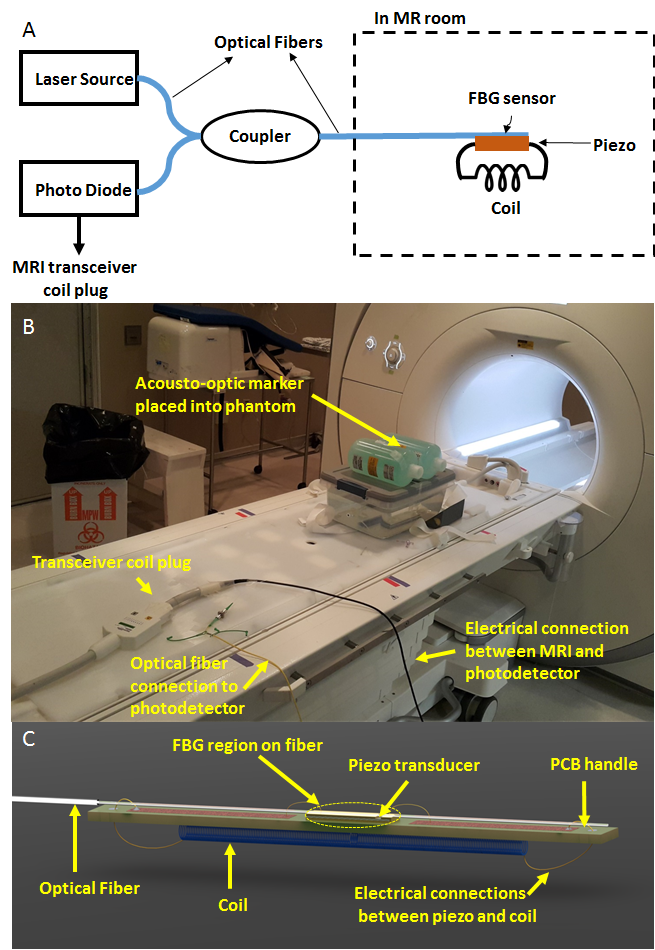
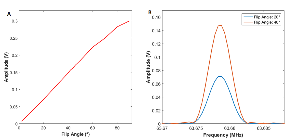
The proposed acousto-optic active MR marker consists of a loop coil, a piezoelectric transducer and a Fiber Bragg Grating (FBG) sensor at the distal end of an optical fiber (Figure 1). An external laser is coupled to the FBG sensor and the reflected light is monitored by a photodetector. The received MR signal through the coil is converted to elastic waves in the optical fiber by a piezoelectric transducer. The piezoelectric transducer is electrically connected to the coil and mechanically connected to the optical fiber sensor. Elastic waves in the FBG region of the fiber modulates the reflected light intensity which is converted to electrical signal by a photo detector at the proximal end of the optical fiber and fed to the transceiver coil plug of the MRI scanner. Since the received MRI signal is converted to an optical signal at the distal end and is carried out using an optical fiber up to photo detector, RF induced heating is intrinsically eliminated. The π-phase shifted FBG sensor used has 250 MHz bandwidth and central wavelength of 1550 nm (Teraxion Inc., Quebec, Canada), and it is embedded in an optical fiber with a diameter of 125 μm cladding and 250 μm of a polymer jacket for protection. The FBG sensor provides high sensitivity for acousto-optic modulation as compared to regular interferometric sensors. A 100 μm thick piezoelectric transducer with 1 mm x 2 mm lateral size (Boston Piezo Optics Inc., MA, USA) was used around its third harmonic resonance (63 MHz) to convert the RF signal to elastic waves around the Larmour frequency. The distal solenoid coil has a length of 10 mm and diameter of 3 mm. Figure 1C shows the detailed drawing of the MR marker for testing in a 1.5 T MRI scanner (Aera, Siemens Healthcare Systems). The visibility performance of the proposed system was compared to an active marker with an identical tuned coil connected to a 50 ohm coaxial transmission line using Gradient Echo (GRE) sequence with following parameters: Flip Angle, 90°:TR, 150 ms; TE, 3.4 ms for acousto-optic marker and Flip Angle, 15°; TR, 150ms; TE, 3.4 ms for active marker. Initial MRI images were collected with 32 averages. The signal levels during same GRE sequence with parameters: TR, 288 ms; TE, 1.1 ms with different flip angles (between 2° and 90 °) were recorded to confirm linearity.Results
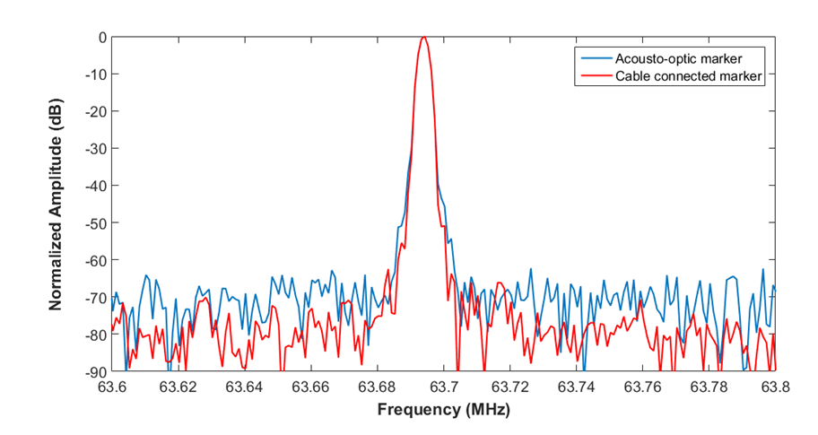
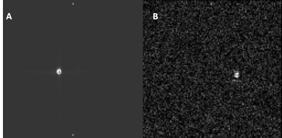
The coupling strength of the RF transmission signal was measured with both acousto-optic and cable connected active markers for comparison (Figure 2). Although measured signal amplitude levels are different, there is only 10 dB difference in SNR values; 70 dB for acousto-optic active marker and 80 dB for active coil. Signal amplitudes follow a linear trend as flip angle is increased as expected (Figure 3). Lastly, echo signal was detected and evidenced by taking MRI images in phantom (Figure 4).Discussion
The inherently RF safe acousto-optic active MR marker was able to capture both transmitted RF signal and echo signal and transmit through the optical fiber. SNR comparison and MRI images shows that sensitivity of the acousto-optic MR marker needs to be improved. This can be achieved by optimizing the coil, and using a piezoelectric transducer with a first harmonic resonance around Larmour frequency to improve electrical-to-mechanical conversion and increasing the sensitivity of acousto-optical modulation by using an FBG sensor with a narrower bandwidth.Conclusion
We performed proof-of-principle experiments for an acousto-optic active marker that can be used to visualize the distal tip of interventional devices while eliminating RF induced heating risk for interventional MRI.Acknowledgements
Research reported in this conference was supported by National Institute of Biomedical Imaging and Bioengineering of the National Institutes of Health under award number R21EB019098. The content is solely the responsibility of the authors and does not necessarily represent the official views of the National Institutes of Health.References
1 Pictet J, Meuli R, Wicky S, van der Klink JJ. Radiofrequency heating effects around resonant lengths of wire in MRI. Phys Med Biol 2002; 47:2973–85.
2 G.S. Kino, Acoustic Waves: Devices, Imaging, and Analog Signal Processing, p. 501-526, 1987.
Figures