0007
MRI-monitored Anterior Cervical Discectomy and Fusion (ACDF) surgery: Observation of intra-procedural nerve decompression during surgery1Radiology, Brigham and Womens Hospital, Boston, MA, United States, 2Orthopedic Surgery, Brigham and Womens Hospital, Boston, MA, United States, 3MRI, Siemens Healthcare, Boston, MA, United States
Synopsis
ACDF is a surgical procedure performed when herniated disks produce severe pain, or arm/hand weakness. Severe complications occur in ~9% of cases, mainly due to tissue resection adjoining the spinal canal. MRI imaging, performed at several procedure stages, can visualize the extent of resection, and the degree of nerve decompression. We performed ACDF surgery on the MRI table, using an MRI-compatible tool-set. Imaging at 3T was performed at four procedure phases. Imaging disclosed significant spine decompression immediately after disk resection, with smaller changes after osteophyte and posterior longitudinal ligament removal. MRI-monitored ACDF can revise procedure phases, leading to improved outcomes.
Purpose
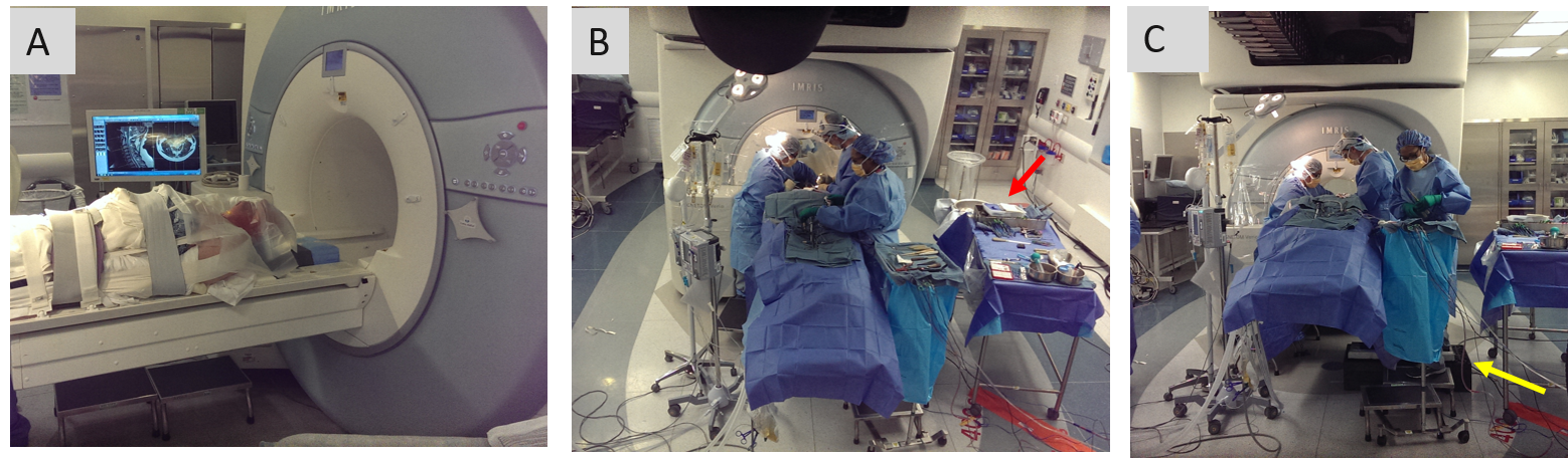
Anterior Cervical Discectomy and Fusion (ACDF) is performed on 150,000 patients/yr (USA)1. ACDF procedures involve (a) displacement of the neck muscles, trachea, and esophagus to access the disc, (b) vertical retraction of neighboring vertebrae to reduce pressure on the culprit disc, (c) complete removal of the herniated disk, (d) removal of osteophytes lining the foramen, (e) removal of the posterior longitudinal ligament (PLL), prior to (f) insertion of a bone-graft in-place of the disc, which is (g) anchored by a metallic plate screwed to neighboring vertebrae. Stages d and e are performed close to the cord. Severe ACDF complications2 occur in 8.7% of patients, due to spinal hematomas or spinal/laryngeal nerve injury. ACDF procedures are completed in 2-2.5 hours2. Controversy exists in the surgical community as to the necessity of e3. We aim to use intraprocedural MRI to study the effects of ACDF procedure stages on spinal nerve decompression, as well as on complications, in order to improve patient outcome and possibly modify/eliminate some stages. The goal is to perform imaging at four procedure phases (stages a, c, d, e), without extending its duration by >1.5 hrs, necessitating fast transitions between surgery and imaging. We choose to operate on the MRI table, with the patient head-first, [Fig. 1] placing the neck <0.5m from the 3T gantry, enabling <15 min surgical intermissions at the desired phases for imaging. The MRI-environment requires the tool-set, which employs large metallic instruments (drill bits, retractors, curettes, rongeurs, and spinal screws) be non-ferrous. Devices which remain in-situ during imaging should exhibit low para-magnetism.Methods
The MRI-compatible ACDF tool-set and its testing. We purchased or built an entire ACDF tool-set exclusively of low-para-magnetic/diamagnetic (titanium, tungsten, carbon fiber) materials, and tested them for MRI-compatibility. This included retractors, curettes and rongeurs. Since appropriate drill bits were unavailable, we used a Sonopet (Stryker, Kalamazoo, MI) irrigated ultrasonic aspirator with a bone tip. We mass-loaded the Sonopet’s ferromagnetic foot-pedal. Devices that stayed in-place during imaging (retractors, distractors, screws) were imaged inserted into a watermelon-based-phantom emulating the human torso, neck and head, along with fiber-optic temperature sensors. We scanned the phantom with a 4.3 W/kg SAR Steady State Free Precession (SSFP) sequence for 37 minutes, detecting temperature increases of <1.50C, within ISTM/IEC limits for MRI-compatibility. We purchased work platforms, allowing surgeons and assistants to operate on the elevated MRI-diagnostic table. Finally, we performed an ACDF procedure in a conventional operating-room using the above equipment, validating that it suited all the surgeon’s needs.
MRI-pulse sequences for work in a high-paramagnetism, lower SNR environment. We developed MRI sequences to acquire T2-weighted contrast using lower SNR coils, relative to the neck array, due to the need to scan a hyper-extended neck with retractors protruding from the surgical cavity. A sterilely-wrapped body-array rested on the chin (anterior-neck-coverage), with the spine array below (posterior-neck-coverage). 2D FSE sequences employing broader-bandwidth or View-Angle-Tilting4, and 3D Wide-band-SSFP sequences5, were developed to reduce metal distortions, and tested with retractors and screws inserted into ex-vivo caprine necks.
The MRI-monitored ACDF procedure [Figure 1]. Procedure was conducted with IRB (N=15) approval. With the patient awake, diagnostic MRI was performed, locating the cervical disk to be resected, which was marked on the skin. The patient was then anesthetized and intubated. Before cutting the skin and displacing the trachea, imaging was performed, providing a pre-surgical baseline (Phase I) for the spinal condition. The vertical retractor’s screws were inserted into the adjoining vertebrae, and the horizontal and vertical retractors were expanded. The herniated disc was then resected completely, followed by MRI Imaging (Phase II). The osteophytes on both foraminal sides of the canal were then removed, followed by MRI imaging (Phase III). The PLL was then removed, followed by MRI Imaging (Phase IV). After completion of the resection, a bone graft was inserted, with an anterior plate screwed between adjoining vertebrae.
Results
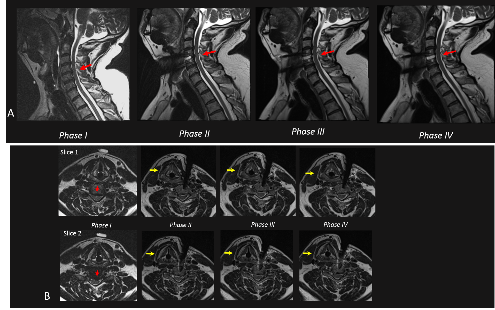
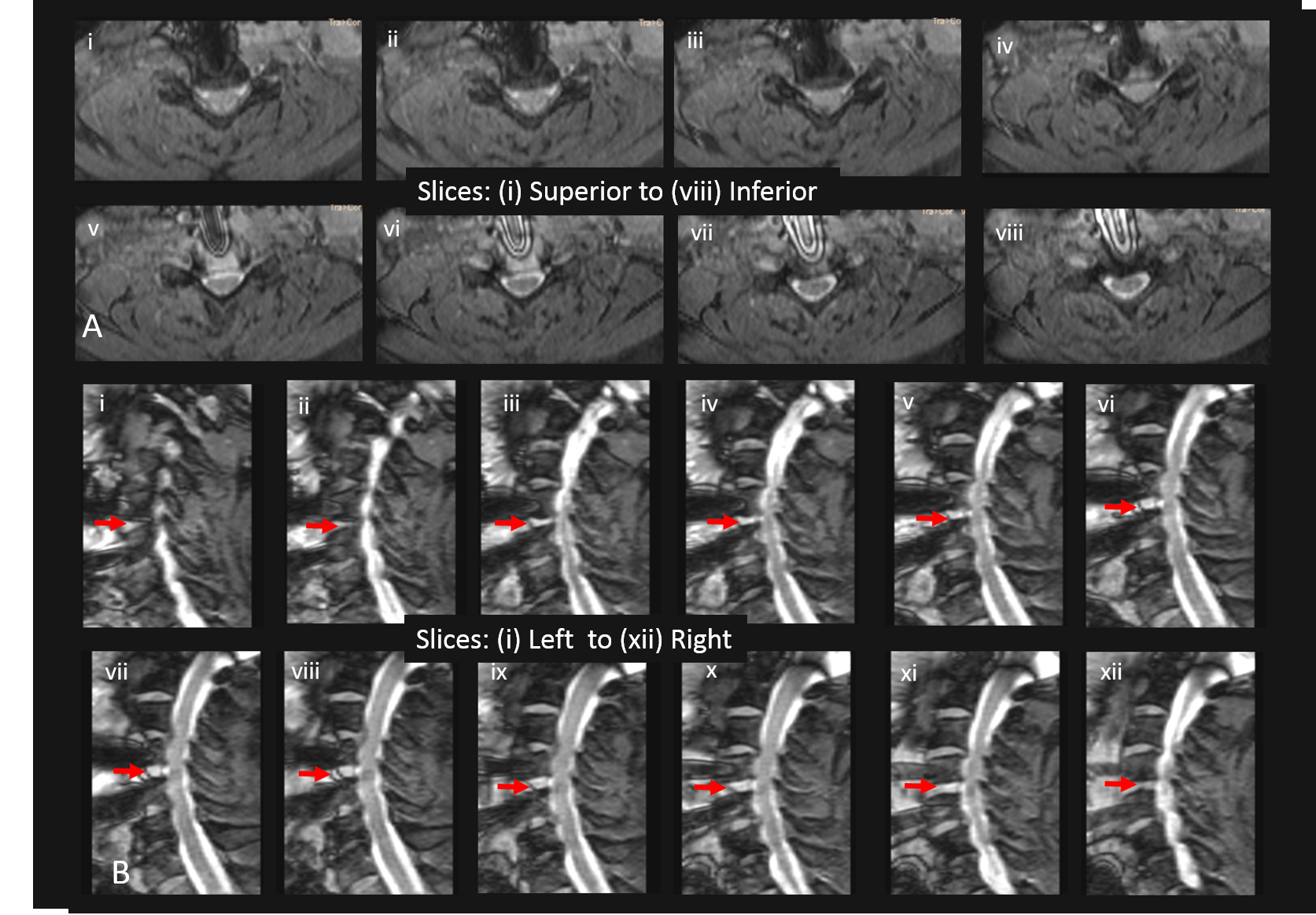
Intra-procedural Imaging results. Figure 2 A,B shows T2-weighted FSE images acquired in Phases I-IV. Despite blood remnants in the resected disc space, excellent spinal canal visualization was obtained, with minimal geometric distortion. Large degree of cord decompression and increased CSF flow was observed in Phase II (after disk resection), with smaller improvements observed in Phases III (after osteophyte removal) and IV (after PLL resection). Figure 3A,B shows high-resolution fat-suppressed Wide-band-SSFP (susceptibility-insensitive neurography) slices in Phase IV, reformatted along axial and sagittal directions, demonstrating csf flow and decompressed nerves.Conclusions
Frequent and efficient intra-procedural MRI monitoring of ACDF procedures is possible, providing immediate feedback on the results of surgical intervention. Surgical phases may be modified, possibly reducing complications.Acknowledgements
NIH P41EB015898References
1. Fountas KN, Kapsalaki EZ, Nikolakakos LG, et al.,Anterior Cervical Discectomy and FusionAssociated Complications, Spine 2007;32:2310-2317
2. Lukasiewicz AM, Basques BA, Bohl DD, et al., Myelopathy Is Associated With Increased All-Cause Morbidity and Mortality Following AnteriorCervical Discectomy and Fusion, Spine 2015: 40,443-449
3. Avila MJ, Skoch J, Sattarov K, et al., Posterior longitudinal ligament resection or preservation in anterior cervical decompression surgery, J Clin. Neurosci. 2015;22:1088-90.
4. Butts K, Pauly J, Gold G, Reduction of Blurring in View Angle Tilting MRI with Multiple View Angle Tilting Readouts, MRM, 2005;53(2):418-24.
5.Danagoulian G, Qin L, Nayak K, Colen R,et al., Comparison of wideband steady-state free precession and T(2) -weighted fast spin echo in spine disorder assessment at 1.5 and 3 T, Mag. Res. Med. 2012;68:1457-1483
Figures