5054
Limitations of 2-D Field Structure Assumptions in Electrical Properties Tomography and its 3-D CSI-EPT Solution1Delft University of Technology, Delft, Netherlands, 2Radiology, Leiden University Medical Center, Leiden, Netherlands
Synopsis
CSI-EPT was originally implemented in a two-dimensional formulation and has since been extended to 3-D to allow for volumetric reconstructions without any assumptions on the field structures. Since the 3-D method is computationally much more complex than its 2-D counterpart, here we investigate the 2-D assumption and its requirements. Unfortunately the 2-D assumption breaks down when the object in consideration is not sufficiently longitudinally invariant, even if the fields can still be considered E-polarised. Therefore, to achieve accurate and robust reconstructions of EPs in a practical or clinical setting the 3-D CSI-EPT method is a recommended starting point.
Introduction
CSI-EPT is an Electrical Properties Tomography (EPT) reconstruction method that uses a Contrast Source Inversion (CSI) optimization approach to retrieve the conductivity and permittivity profiles of tissue based on $$$B_1^+$$$-data. The method can handle variations in tissue profiles and was originally implemented for profile reconstructions in the midplane of a birdcage coil, where the RF field exhibits an E-polarized field structure1. Recently, CSI-EPT has been extended to a fully 3-D volumetric reconstruction method that is generally applicable (in- or outside the midplane) and no particular field structure or smoothness is assumed2. This is a major step towards turning CSI-EPT into a practical reconstruction method. Unfortunately, the computation times significantly increase (hours or even days, depending on the reconstruction domain of interest) and from this point of view a 2-D approach3 may be preferable. We show, however, that a 2-D approach is only warranted under very specific circumstances and having an E-polarized field structure is a necessary but not sufficient condition. In particular, we show that to obtain accurate tissue reconstructions based on 3-D $$$B_1^+$$$ data, it is in general necessary to take all electromagnetic field components into account and a 2-D reconstruction approach will lead to reconstruction artefacts.Methods
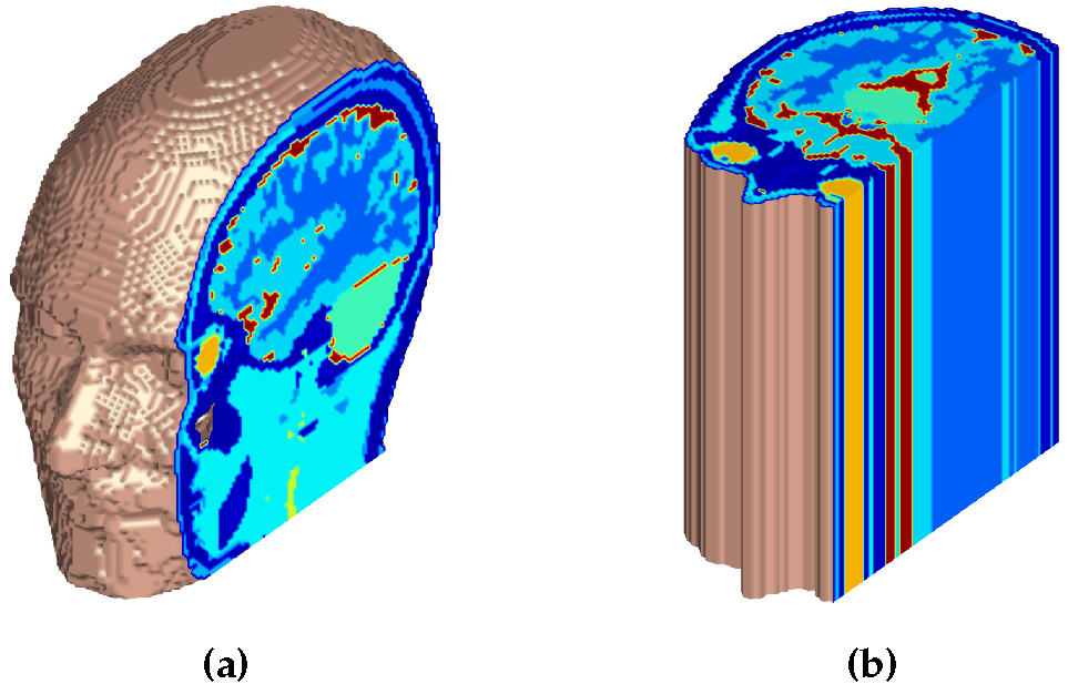
We use 2-D and 3-D CSI-EPT to reconstruct tissue profiles within a realistic male head model (Virtual Family4) consisting of 124x100x109 voxels (2x2x2 mm3; Model A, Figure 1a). To investigate the consequences of a 2-D assumption, a longitudinal homogeneous head model (Model B, Figure 1b) is considered as well in which the center slice is extended in the longitudinal direction. The RF fields are generated by an ideal birdcage coil driven in quadrature at 128 MHz and are computed using XFdtd software (Remcom5).
In CSI-EPT an objective function is minimized, which consists of a data and consistency mismatch term. The modeled data is computed as$$B_1^{+;\text{sc}}=\frac{\omega}{c_0^2}\left(\partial^+A_z^{\text{sc}}-\partial_zA^{+;\text{sc}}\right)\qquad\text{[3-D]}\quad\text{and}\quad\,B_1^{+;\text{sc}}=\frac{\omega}{c_0^2}\partial^+A_z^{\text{sc}},\qquad\text{[2-D]}$$which are obtained from the Maxwell field representations $$\mathbf{B}^{\text{sc}}=\text{j}\frac{\omega}{c_0^2}\mathbf{\nabla}\times\mathbf{A}^{\text{sc}}\qquad[\text{3-D}]\quad\text{and}\quad\mathbf{B}^{\text{sc}}=\text{j}\frac{\omega}{c_0^2}\mathbf{\nabla}_{\text{T}}\times\mathbf{A}^{\text{sc}}\qquad[\text{2-D}].$$The consistency term is evaluated using$$\mathbf{E}^{\text{sc}}=(k_0^2+\mathbf{\nabla}\mathbf{\nabla}\cdot)\mathbf{A}^{\text{sc}}\qquad\text{[3-D]}\quad\text{and}\quad\mathbf{E}^{\text{sc}}=k_0^2\mathbf{A}^{\text{sc}}.\qquad\text{[2-D]}$$Here, $$$\mathbf{A}^{\text{sc}}$$$ is the scattered electric vector potential, $$$A^{+;\text{sc}}=\frac{1}{2}(A_x^{\text{sc}}+\text{j}A_y^{\text{sc}})$$$, $$$\nabla_{\text{T}}$$$ the transverse nabla operator, and $$$k_0$$$ the wave number of the surrounding medium. From these representations it is immediately clear that the gradient-divergence term in the E-field representation is absent in 2-D as opposed to a 3-D formulation and longitudinal variations of the vector potential are also ignored.
Results & Discussion
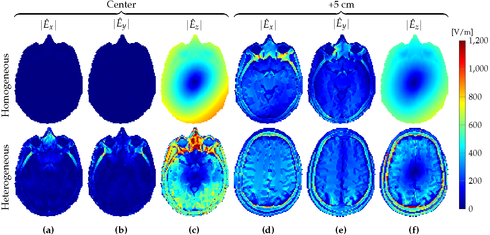
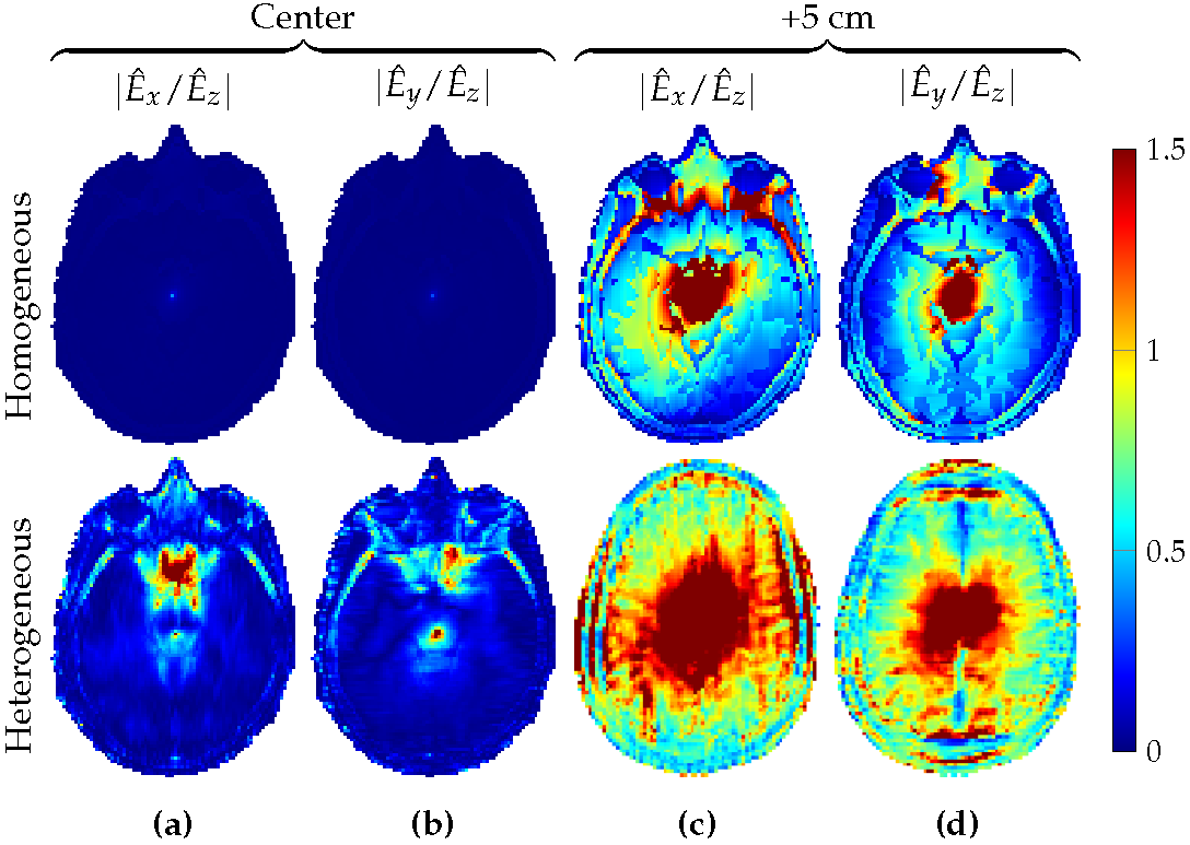
In model B, the 3-D field indeed has an E-polarized field structure in the center slice (top row, Figure 2a--c). For model A, the electric field has nonnegligible transverse components in this slice (bottom row, Figure 2a--c), which are absent for a purely E-polarized field. In a slice five centimeters above the center slice, however, E-polarized field structure is completely lost for both head models (Figure 2d--f) showing that there are longitudinal variations. Figure 3 confirms these findings by showing the magnitude of the $$$x$$$- and $$$y$$$-components of the E-field relative to the magnitude of its $$$z$$$-component. Only in the center slice for a $$$z$$$-invariant object the $$$x$$$- and $$$y$$$-components of the electric field may be neglected.
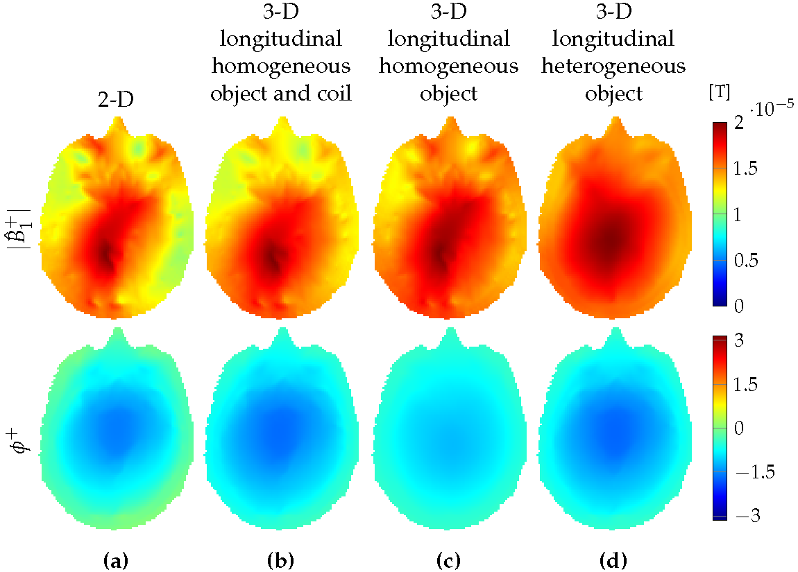
Furthermore, in Figure 4a we show the $$$B_1^+$$$ field distribution in the center slice for a 2-D setup, where both the model and the rungs of the coil extend to infinity in the longitudinal direction and compare this 2-D field with the $$$B_1^+$$$-field obtained with Model B and long but finite rung lengths in the longitudinal direction (Figure 4b). In this case, the $$$B_1^+$$$-field structure is similar to a 2-D field structure. However, if we replace the ``long-rung coil" by a realistic coil, but keep Model B, the $$$B_1^+$$$-field pattern starts to change (Figure 4c). For Model A, large deviations in the $$$B_1^+$$$ field pattern are observed compared with its 2-D counterpart (Figure 4d).
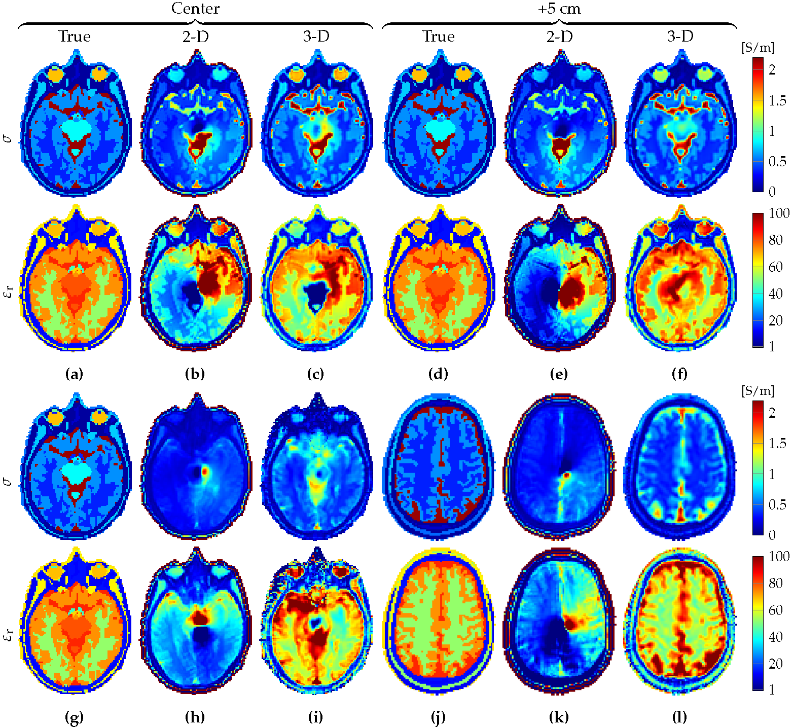
Finally, Figure 5 shows the 2-D and 3-D conductivity and permittivity reconstructions for both models within the center slice and a slice 5 centimeters above. We observe that if 2-D CSI-EPT is used, large reconstruction errors are obtained and only 3-D CSI-EPT is able to accurately reconstruct the tissue profiles.
Conclusion
Reliable tissue reconstructions can be obtained with 3-D CSI-EPT without making invariance or smoothness assumptions. Its 2-D counterpart is computationally more efficicient, but we have shown that its applicability is rather limited and similarities between 2-D and 3-D field structures are not sufficient for 2-D CSI-EPT. The computational costs of 3-D CSI-EPT can be alleviated by including preconditioning techniques and improved initial guesses. Future work will focus on turning 3-D CSI-EPT into a clinically applicable EPT imaging modality by incorporating these techniques along with coil loading effects and transceive phase correction mechanisms.Acknowledgements
The research of R.L. Leijsen was funded by European Research Council Advanced NOMA MRI under grant number 670629. The research of P.S. Fuchs was funded in part through a collaboration between the Delft University of Technology and the Indian Institute of Science.References
1Balidemaj E, van den Berg CAT, Trinks J, et al. CSI-EPT: A Contrast Source Inversion Approach for Improved MRI-Based Electric Properties Tomography. IEEE Tran Med Im. 2015;34(9):1788-1796.
2Leijsen RL, Brink WM, van den Berg CAT, et al. 3-D Contrast Source Inversion-Electrical Properties Tomography. IEEE Tran Med Im. 2018;37(9):2080-2089.
3Fuchs PS, Mandija S, Stijnman PRS, et al. First-Order Induced Current Density Imaging and electrical Properties Tomography in MRI. IEEE Tran comp Imag. 2018.
4Christ A, Kainz W, Hahn EG, et al. The virtual family development of surface-based anatomical models of two adults and two children for dosimetric simulations. Phys Med Biol. 2010;55(2):23-38.
5XFdtd, Remcom State College, PA, USA.
Figures