4639
Universal Parallel Transmit Pulse Design for 3-Dimensional Local-Excitation – A 9.4T Simulation Study1Hochfeld-Magnetresonanz, Max-Planck-Institut für biologische Kybernetik, Tübingen, Germany
Synopsis
This study introduces a parallel-transmission (pTx) radio-frequency (RF) pulse-design-method to create an universal pTx RF-pulse that excites the same 3-dimensional local excitation pattern with a desired flip-angle in different human heads at 9.4T. Thus, it prospectively abandons the need for time-consuming subject specific B1+ mapping and pTx-pulse calculation during the scan session. The resulting universal pulses created magnetization profiles with an only marginal worse Normalized-Root-Mean-Square-Error (NRMSE) compared to the magnetization profiles produced by the pulses tailored to individual heads.
Introduction
Parallel-transmission (pTx) systems offer additional degrees of freedom for designing tailored RF-pulses (TPs). However, pTx-pulse-design often includes measuring the B1+field distribution for each subject. In addition, the pulse calculation is currently performed during the scan-session. That leads to lengthy scan times and prevents clinical- and research-applications of pTx. Gras et al.1,2 introduced the concept of ‘universal’ pTx-pulses, which does not require the knowledge of channel-wise B1+distribution in individual subjects, and rather relies on a pre-calculated pulse-database. However, these studies only considered the case of homogenous whole-brain excitation pulses that mitigate B1+inhomogeneity. In an own previous study3, we extend the universal pulse design concept to 2-dimensional local excitation. In this study, we investigate parallel-transmit 3-dimensional (3D) local-excitation-pulses and present a possibility to design a calibration-free ‘universal’ pTx-pulse (UP) which consistently excites the same local 3D pattern with a desired flip-angle (FA) in four different heads.Methods
For four different heads of healthy volunteers the B1+maps from each transmit channel of an 8-channel RF-coil4 were measured using a 9.4T whole body MRI scanner.
The goal was to design a single pTx-RF-pulse that would consistently excite the same 3D local pattern with a desired FA in these four heads.
Two 3D local excitation test-target-patterns where chosen: A cuboid in the center of each head and a cylinder reaching from the top to the bottom of each head. For both patterns an UP with a desired FA of 10 (FA10) and 90 (FA90) degrees, respectively, were designed. Afterwards the performances of the UPs were compared with the performances of the TPs by calculating the Normalized-Root-Mean-Square-Error (NRMSE) between the resulting magnetization profiles and the target-patterns.
To calculate the UPs the spatial domain method5 and additive angle method6 of Grissom et al. was extended to include more than one subject for which the pulse is optimized.
To design a pulse tailored to one subject, in Grissom et al.5,6 the aim was to solve the minimization problem
$$b^{* }_{TP}=\underset{b}{\arg\max}\{||Ab-m_{des}||^2\},\quad Eq.1$$
with:
- $$$A$$$ is the system-matrix that arises from discretization of the small-tip-angle-approximation, it contains the subjects B1+,B0, the spatial and the gradient information,
- $$$b$$$ is the pulse-vector,
- $$$m_{des}$$$ is the target-pattern.
The idea in this study was to solve the minimization problem for all four subjects at the same time to design the UP:
$$b^{* }_{UP} = \underset{b}{\arg\max}\left\{\left|\left|\begin{bmatrix} A_1 \\A _2\\ A_3\\A_4 \end{bmatrix}b-\begin{bmatrix} m_{des} \\m_{des}\\m_{des}\\m_{des}\end{bmatrix}\right|\right|^2\right\},\quad Eq.2$$
($$$A_i$$$ is the system-matrix for subject $$$i =1,\dots ,4,$$$ $$$b$$$ and $$$m_{des}$$$ as described above).
The problem was solved with Matlabs lsqr-function. The resulting pulse was used as an initial pulse for the optimal-control pulse-design method GRAPE7,8 (implemented that it designs the pulse based on all four subjects) to improve the pulse performance.
The pulses tailored to one specific subject was designed similarly.
First, Grissom et al.5,6 methods were applied (Eq. 1) and afterwards
the GRAPE-algorithm was executed.
3D-stack-spiral-in k-space-trajectories and a pulse-duration of 8.02 (for cuboid) and 2.21 ms (for cylinder), were choosen. T1- and T2-relaxation times were not considered during this 9.4T simulation-study.
Results
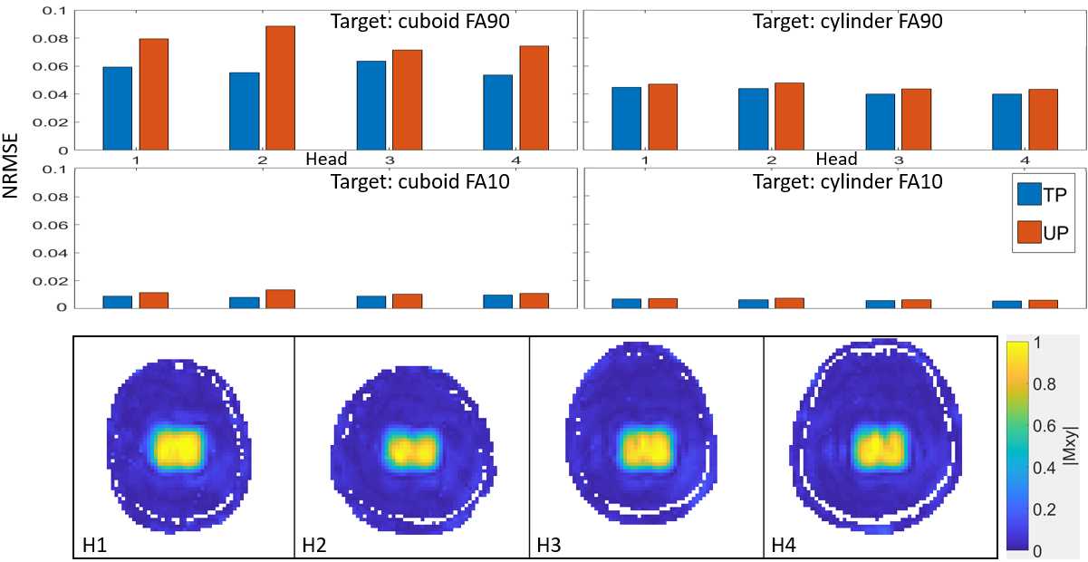
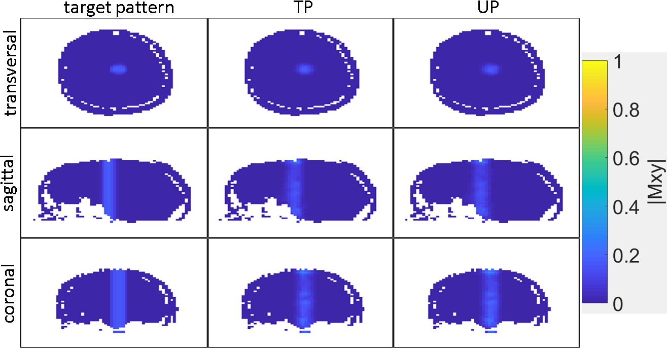
As depicted in figure 1, the performance of the TP versus the UP is highly similar for all cases. The highest NRMSEs occur for the cuboid target-pattern with FA90. For instance, on head 1 (H1) the respective TP performs with a NRMSE of 0.059, which is only slightly better than the UP-performance with a NRMSE of 0.08.
The lowest NRMEs are achieved for the cylinder target-pattern with FA10. Here, on H1 the TP performs with a NRMSE of 0.0069, the UP performs with a NRMSE of 0.0073.
The bottom row of figure 1 shows the performance of the UP for cuboid target-pattern with FA90 on the four heads.
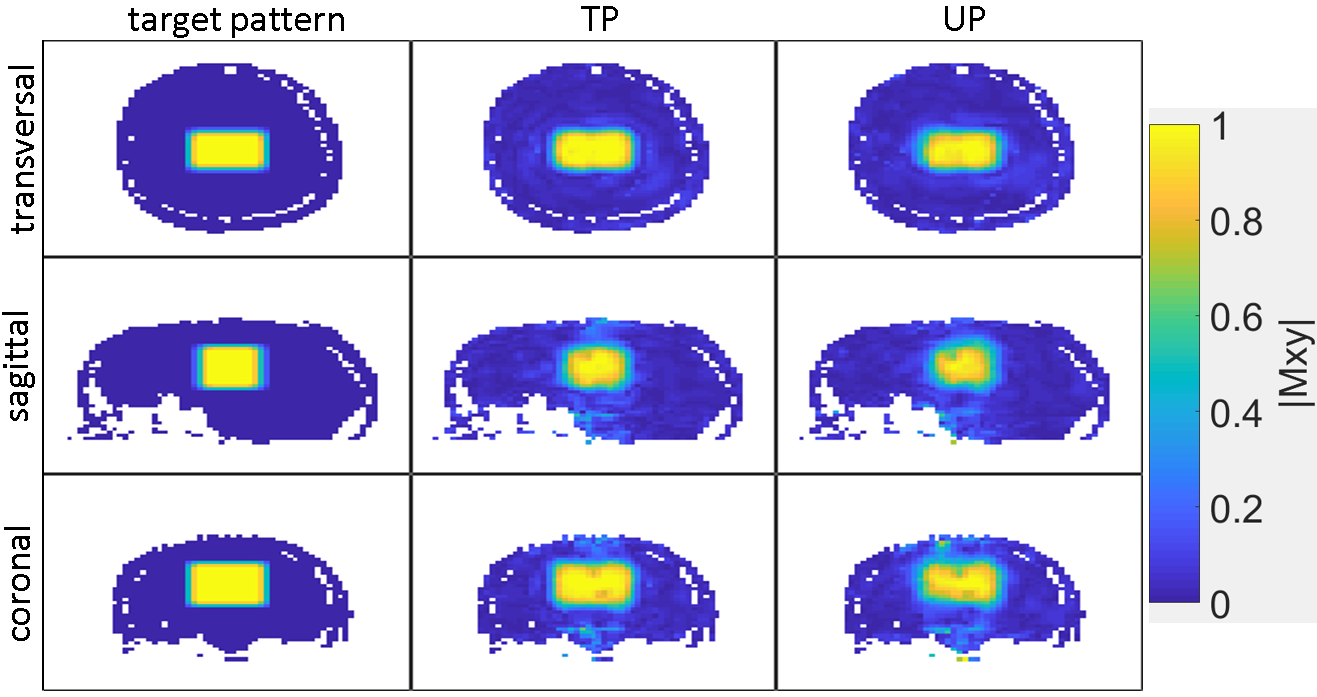
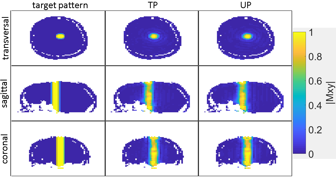
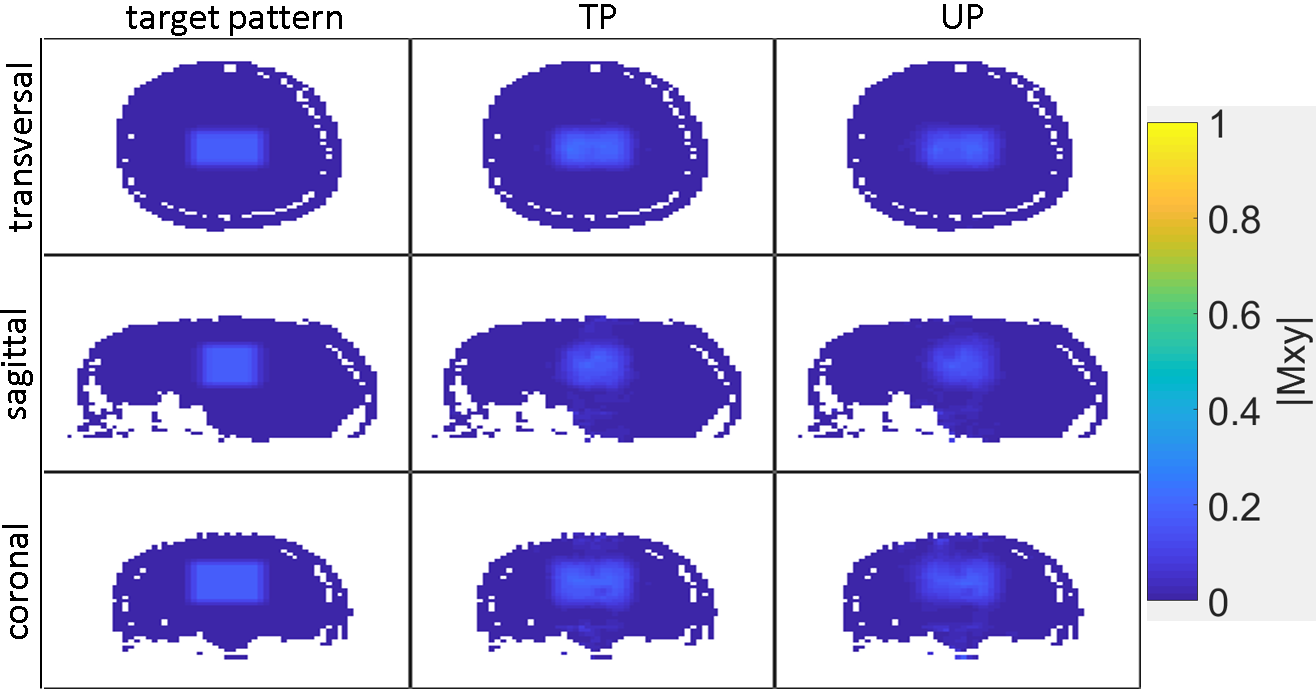
In figures 2, 3, 4 and 5 the respective magnetization profiles for all combinations of target-pattern and FA are presented for H1.
Discussion
For each head and target the performances of the UPs is only marginal worse compared to the TPs performances. The cuboid target pulses show a lower performance than the cylindrical target pulses, while the FA90 pulses show larger deviations from the target than the FA10 pulses.Conclusion
The proposed UP-design routine creates reliably pulses that achieve the same 3D-local-excitation pattern with a desired FA across different heads. Thus, we demonstrated, that it is possible to design 3D-pulses which have the same effect on different subjects. By creating pTx-pulse-databases optimized for larger subject cohorts the time-consuming per subject B1+map-measurements can potentially be eliminated from the PTx-scan-sessions in future. This significantly reduces the scan time, abandons the need of subject specific pulse optimization while the subject is waiting in the scanner and might open up new possibilities in the field of PTx-pulse-design.Acknowledgements
Funding by the European Union (ERC Starting Grant, SYNAPLAST MR, Grant Number: 679927) is gratefully acknowledged.References
1. Gras V, Vignaud A, Le Bihan D, Boulant N. Universal Pulses: A New Concept for Calibration-Free Parallel Transmission. Magnetic Resonance in Medicine. 2017; 77:635-643.
2. Gras V, Mauconduit F, Vignaud A, Amadon A, Le Bihan D, Stöcker T, Boulant N. Design of Universal Parallel-Transmit Refocusing kT-Point Pulses and Application to 3D T2-Weighted Imaging at 7T. Magnetic Resonance in Medicine. 2017; 00:00–00.
3. Geldschläger O, Shao T, Henning A. Universal Parallel Transmit Pulse Design for Local Excitation. In: Proceedings of Joint Annual Meeting ISMRM-ESMRMB 2018, Paris, France, 2018. p 3395.
4. Avdievich NI, Giapitzakis IA, Pfrommer A, Borbath T, Henning A. Combination of surface and ‘vertical’ loop elements improves receive performance of a human head transceiver array at 9.4 T. 2018; NMR in Biomedicine. 31(2): 1-13.
5. Grissom W, Yip C, Zhang Z, Stenger VA, Fessler JA, Noll DC. Spatial domain method for the design of RF pulses in multicoil parallel excitation. Magnetic Resonance in Medicine. 2006;56:620–629.
6. Grissom WA, Yip C-J, Wright SM, Fessler JA, Noll DC. Additive Angle Method for Fast Large-Tip-Angle RF Pulse Design in Parallel Excitation. Magnetic Resonance in Medicine. 2008; 59:779–787.
7. Xu D, King KF, Zhu Y, McKinnon GC, Liang Z- Designing multichannel, multidimensional, arbitrary flip angle RF pulses using an optimal control approach. Magnetic Resonance in Medicine. 2008; 59:547–560.
8. Khaneja N, Reiss T, Kehlet C, Schulte-Herbruggen T, Glaser SJ. Optimal control of coupled spin dynamics: design of NMR pulse sequences by gradient ascent algorithms. Journal of Magnetic Resonance. 2005; 172:296–305
Figures