4635
Redesigned Variable-Density Cones Trajectory for High Resolution MR Imaging1Magnetic Resonance Systems Research Lab (MRSRL), Department of Electrical Engineering, Stanford University, Stanford, CA, United States, 2Department of Bioengineering, Stanford University, Stanford, CA, United States, 3Department of Radiology, Stanford University, Stanford, CA, United States
Synopsis
The 3D cones trajectory has been employed for various applications. In this work we transform the task of designing the cones trajectory into a generic procedure of discretizing an analytic coordinate. We present a new discretization scheme with a spiral path on a unit sphere, which enables allocation of readout interleaves on distinct conic surfaces for any given number of readouts. Subsequently, we derive the relationship between the sampling density of each interleaf and that of overall interleaves, which allows us matching the sampling density of the cones trajectory to the 1/f-model of 3D images.
Introduction
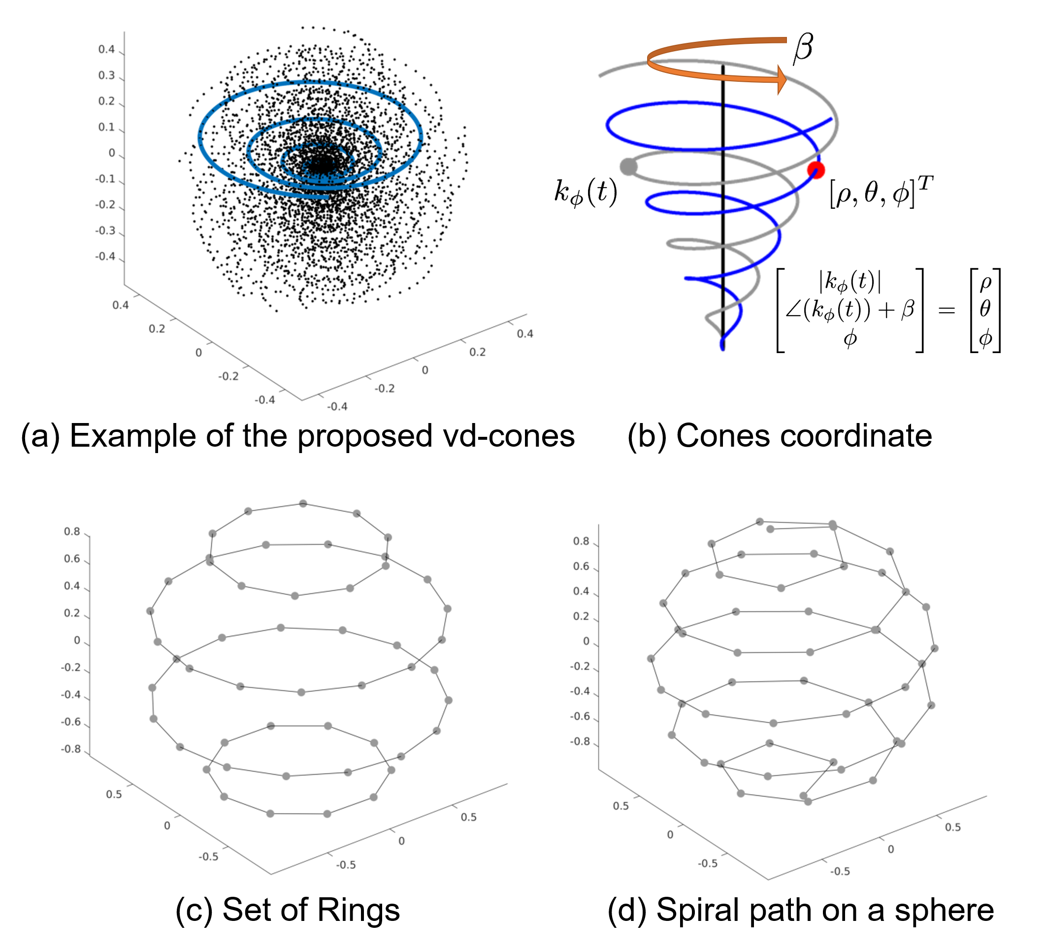
The 3D cones trajectory [1] has been employed for various applications [2, 3, 4]. In this work we transform the task of designing the cones trajectory into a generic procedure of discretizing an analytic coordinate [5]. We present a new discretization framework that uses a cones coordinate [5] and a spiral path on a unit sphere, which enables allocation of readout interleaves on distinct conic surfaces and generates a more uniformly distributed trajectory [6]. In contrast to phyllotaxis cones trajectory [6], the number of readouts need not be identical or similar to a Fibonacci number.
We also consider the relationship between the sampling density of each conic interleaf and that of the collective set of interleaves. More specifically, the analytic form of the density compensation factor [5] is derived with variable-density (vd) cones. The sampling density of conic interleaves are matched to the $$$1/k_r$$$-model [7] of 3D images. An example of the proposed trajectory is illustrated in Figure 1(a).
Theory: Discretization of Cones Coordinate
We propose a cones coordinate $$$(t, \beta, \phi)$$$ that represents a point in 3D space with a rotation of a template spiral on a conic surface [5, 8] as illustrated in Figure 1(b). The construction of the cones trajectory is then reduced to discretization of the cones coordinate [5].
The trajectory previously proposed in [5] can be
suboptimal since the locations of $$$(\beta, \phi)$$$ are confined to a set of
rings (Figure 1(c-d)). We propose a new approach based on the one-to-one
relationship between spherical and cones coordinates:
$$\begin{align} \begin{bmatrix} \rho \\ \theta \\ \phi \\ \end{bmatrix} &= \begin{bmatrix} |\vec{k}_{\phi}(t)| \\ \angle(\vec{k}_{\phi}(t)) + \beta \\ \phi\\ \end{bmatrix},\end{align}$$ which shows that the discretization of the cones coordinate is equivalent to sampling points on a unit sphere.
This problem can be solved by formulating a spiral path on the sphere [9]:$$\begin{align} \begin{bmatrix} x_s(u) \\ y_s(u) \\ z_s(u) \\ \end{bmatrix} &= \begin{bmatrix} \cos\beta_s(u) \sin\phi_s(u) \\ \sin\beta_s(u) \sin\phi_s(u) \\ \sin\phi_s(u)\\ \end{bmatrix}\end{align}$$
We can prove that the following algorithm gives the desired cones trajectory:$$\begin{align}\phi_s(u) &= \mbox{Inverse Function}(u(\phi))\\ u(\phi) &= \frac{1}{Z}\int_0^\phi n(x)FOV(x + \pi/2) \mathrm{d}x, \\ Z &= \int_0^\pi n(x)FOV(x + \pi/2) \mathrm{d}x, \\ \beta_s(u) &= \int_0^1 \frac{2\pi N}{w}\frac{1}{n(\phi_s(u))} \mathrm{d}u, \\ w &= \sqrt{\frac{N}{k_{max} Z}},\end{align}$$ where $$$N$$$ denotes the number of readouts and $$$n(\phi)$$$ is the required number of interleaves on the conic surface-$$$\phi$$$.
In contrast to previous approaches [1, 5], each readout is seated on a unique conic surface.
Theory: Variable-Density Cones
We formulate vd-cones in a similar fashion to a 2D spiral trajectory [10, 11]:$$\begin{align}\label{eq:vd_cones_form} \begin{bmatrix} x(t) \\ y(t) \\ z(t) \\ \end{bmatrix} &= \begin{bmatrix} k(t)\cos(\lambda k(t)^{1/\alpha})\sin\phi \\ k(t)\sin(\lambda k(t)^{1/\alpha})\sin\phi\\ k(t)\cos\phi\\ \end{bmatrix},\mbox{ (1)}\end{align}$$ $$$k(t) = \sqrt{k_x(t)^2 + k_y(t)^2 + k_z(t)^2}$$$ can be modelled by using similar approximations in [11, 12]: $$\begin{align} k(t) \propto \begin{cases} t^{\frac{2 \alpha}{\alpha+2}} &\text{slew-rate limit}\\ t^{\frac{\alpha}{\alpha+1}} &\text{amplitude limit} \end{cases}\mbox{ (2)}\end{align}$$
The incorporation of (1) into the density compensation factor (DCF) of the cones trajectory derived in [5] leads to a compact representation of DCF:$$\begin{align} DCF(t,\phi)=k^2(t)\dot{k}(t) \left(\frac{\sin(\phi)}{p(\phi)}\right).\mbox{ (3)}\end{align}$$ With (2) and (3) we derive the relationship between the sampling density of each interleaf and that of the collection of all interleaves:$$\begin{align}DCF(k) \propto \begin{cases} k^{\frac{5\alpha - 2}{2\alpha}} &\text{slew-rate limit}\\ k^{\frac{2\alpha - 1}{\alpha}} &\text{amplitude limit} \end{cases}\end{align}$$
We heuristically choose the sampling density function for the vd-trajectory to match the $$$1/k_r$$$ dependence that generally applies to k-space data of 3D images [7]. In this way, the aliasing energy arising from k-space regions with greater undersampling will be lower. As a guideline, we may choose $$$\alpha$$$ as follows: $$\begin{align} \alpha = \begin{cases} 1 &\text{slew-rate limit}\\ 2 &\text{amplitude limit} \end{cases}\end{align}$$ We used $$$\alpha = 1.5$$$ in the following experiments.Method
A numerical phantom was generated with MRXCAT [13] for the simulation study. A GE 1.5T Signa scanner (Waukesha, WI) was used for the phantom study. An ATR-SSFP sequence [2] was prescribed as follows: TE/TR$$$_1$$$/TR$$$_2 = 0.57/1.15/4.55$$$ms, $$$70^\circ$$$ flip angle, and 2.8ms readout duration.
Standard 3D gridding was used for the simulation study whereas ESPIRiT [14] was applied for reconstructing 8-channel data in the phantom study.
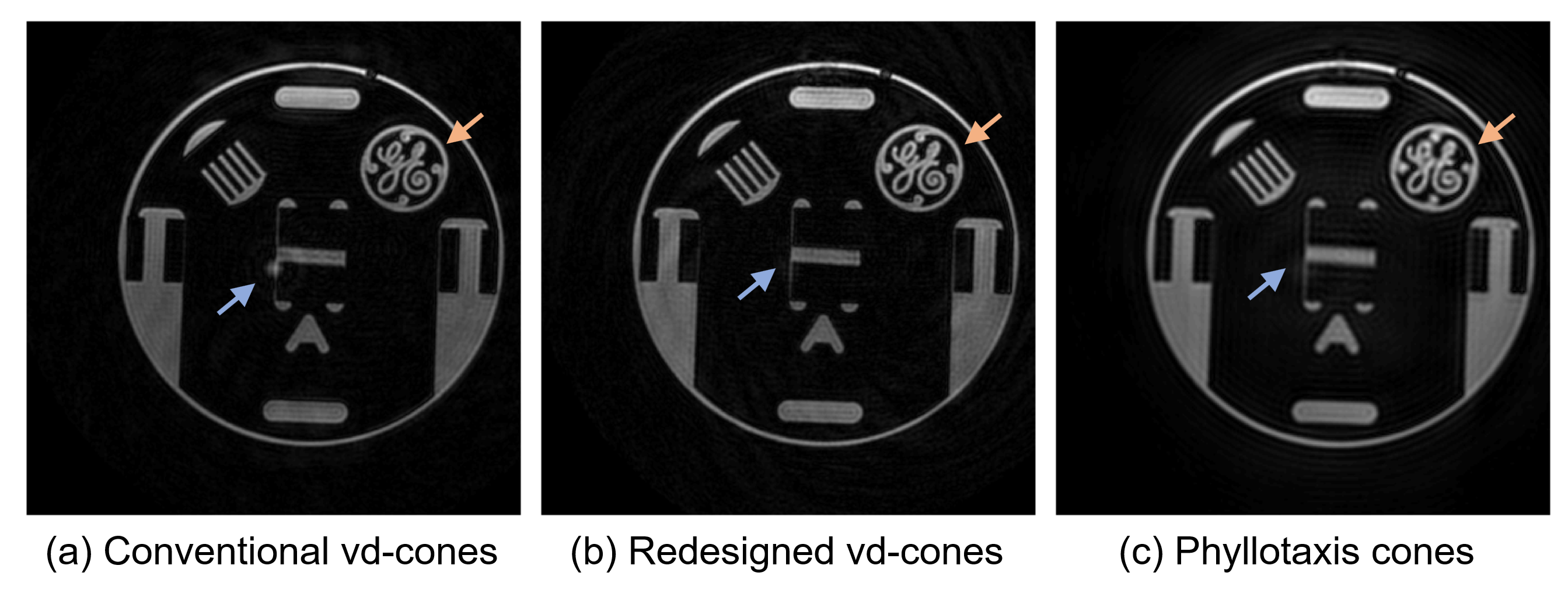
Conventional vd-cones [15] and phyllotaxis cones
trajectories [6] were used as comparisons.
Result
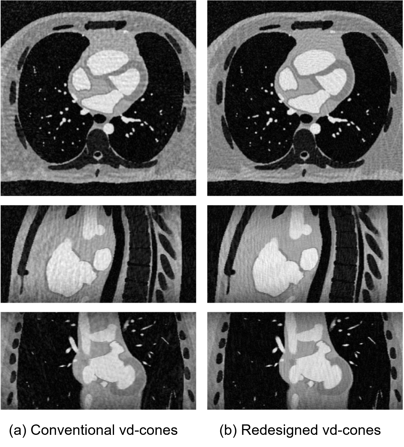
In the simulation study, the redesigned vd-cones displayed less aliasing artifacts as illustrated in Figure 2.
The reconstructed axial slices in the phantom study are given in Figure 3. Both vd-cones trajectories with 0.8-mm resolution provided sharper reconstructions compared to phyllotaxis cones trajectory with 1.2-mm resolution. The proposed trajectory showed less reconstruction artifact at the center compared to the conventional trajectories, thanks to its vd-design with $$$\alpha > 1$$$.
Conclusion
We have developed a new design method for 3D MR imaging with vd-cones. Each interleaf was allocated on a unique conic surface, which results in a more uniformly distributed trajectory.
Acknowledgements
No acknowledgement found.References
[1] P. T. Gurney, B. A. Hargreaves, and D. G. Nishimura, “Design and analysis of a practical 3D cones trajectory,” Magnetic Resonance in Medicine, vol. 55, no. 3, pp. 575–582, 2006.
[2] H. H. Wu, P. T. Gurney, B. S. Hu, D. G. Nishimura, and M. V. McConnell, “Free-breathing multiphase whole-heart coronary MR angiography using image-based navigators and three- dimensional cones imaging,” Magnetic Resonance in Medicine, vol. 69, no. 4, pp. 1083–1093, 2013.
[3] E. J. Zucker, J. Y. Cheng, A. Haldipur, M. Carl, and S. S. Vasanawala, “Free-breathing pediatric chest MRI: Performance of self-navigated golden-angle ordered conical ultrashort echo time acquisition,” Journal of Magnetic Resonance Imaging, vol. 47, no. 1, pp. 200–209, 2018.
[4] C. M. Sandino, J. Y. Cheng, M. T. Alley, M. Carl, and S. S. Vasanawala, “Accelerated abdominal 4D flow MRI using 3D golden-angle cones trajectory,” in Proceedings of the 26th Annual Meeting of the ISMRM, 2017.
[5] K. E. Jang, D. G. Nishimura, and S. S. Vasanawala, “Redesigned Cones Trajectory based on Discretization of Cones Coordinate,” in Proceedings of the 26th Annual Meeting of the ISMRM, 2017.
[6] M. O. Malave, C. A. Baron, N. O. Addy, J. Y. Cheng, P. C. Yang, B. S. Hu, and D. G. Nishimura, “Whole-heart coronary MR angiography using a 3D cones phyllotaxis trajectory,” Magnetic Resonance in Medicine, vol. 0, no. 0, pp. 1–12, 2018.
[7] v. A. Van der Schaaf and J. v. van Hateren, “Modelling the power spectra of natural images: statistics and information,” Vision research, vol. 36, no. 17, pp. 2759–2770, 1996.
[8] R. D. Hoge, R. K. Kwan, and G. Bruce Pike, “Density compensation functions for spiral MRI,” Magnetic Resonance in Medicine, vol. 38, no. 1, pp. 117–128, 1997.
[9] S. T. Wong and M. S. Roos, “A strategy for sampling on a sphere applied to 3D selective RF pulse design,” Magnetic Resonance in Medicine, vol. 32, no. 6, pp. 778–784, 1994.
[10] D. M. Spielman, J. M. Pauly, and C. H. Meyer, “Magnetic resonance fluoroscopy using spirals with variable sampling densities,” Magnetic Resonance in Medicine, vol. 34, no. 3, pp. 388–394, 1995.
[11] D.-h. Kim, E. Adalsteinsson, and D. M. Spielman, “Simple analytic variable density spiral design,” Magnetic Resonance in Medicine: An Official Journal of the International Society for Magnetic Resonance in Medicine, vol. 50, no. 1, pp. 214–219, 2003.
[12] G. H. Glover, “Simple analytic spiral k-space algorithm,” Magnetic Resonance in Medicine, vol. 42, no. 2, pp. 412–415, 1999.
[13] L. Wissmann, C. Santelli, W. P. Segars, and S. Kozerke, “MRXCAT: Realistic numerical phan- toms for cardiovascular magnetic resonance,” Journal of Cardiovascular Magnetic Resonance, vol. 16, no. 1, p. 63, 2014.
[14] M. Uecker, P. Lai, M. J. Murphy, P. Virtue, M. Elad, J. M. Pauly, S. S. Vasanawala, and M. Lustig, “ESPIRiT—an eigenvalue approach to autocalibrating parallel MRI: where SENSE meets GRAPPA,” Magnetic Resonance in Medicine, vol. 71, no. 3, pp. 990–1001, 2014.
[15] N. O. Addy, R. R. Ingle, H. H. Wu, B. S. Hu, and D. G. Nishimura, “High-resolution variable-density 3D cones coronary MRA,” Magnetic Resonance in Medicine, vol. 74, no. 3, pp. 614–621, 2015.
Figures