4633
A Novel Approach to Investigate 1D TRASE MRI Pulse Sequence Performance in Imperfect B1 Fields1University of Saskatchewan, Saskatoon, SK, Canada, 2University of Alberta, Edmonton, AB, Canada
Synopsis
The Transmit Array Spatial Encoding (TRASE) MRI technique uses transmit radio-frequency (RF) magnetic field (B1) phase gradients for spatial encoding. Imaging performance is reliant on |B1| homogeneity. This study investigates the performance of a set of variants of 1-dimensional
Introduction
Transmit Array Spatial Encoding (TRASE) is a novel MRI technique that achieves spatial encoding by introducing phase gradients in the transmit radio-frequency (RF) magnetic field (B1)1. The B1 field can be represented as:
$$ B_{1}=|B_{1}|e^{i\phi\vec{(r)}} $$
where $$$ \phi\vec{(r)} $$$ represents the spatially varying B1 phase of a transmit coil.
The TRASE technique is useful in low-cost, low-field, and portable MRI systems since it no longer requires the use of complex B0 gradient coils used in conventional MRI machines. MRI equipment using TRASE technology have potential applications in remote locations and long-term space flights (monitoring astronaut health on the International Space Station, ISS, and the Moon)2.
A TRASE pulse sequence consists of a long echo train, with each echo sampling a different location in k-space (Figure 1). The imaging performance of TRASE relies on accurate refocusing and hence depends on the |B1| homogeneity throughout the imaging volume. Although composite pulses3 and the Wideband Uniform Rate Smooth Truncation (WURST) pulses4 can reduce TRASE’s sensitivity to |B1| inhomogeneity, their longer duration than rectangular pulses impair achievable spatial resolution. Since some level of B1 field inhomogeneity is inevitable due to transmit coil design constraints, a pulse sequence-based solution to overcome this limitation of TRASE is desirable.
During a TRASE experiment, all phases accumulate across the sample, however, CPMG5 cannot be relied on to provide immunity against |B1| inhomogeneity because this sequence preserves only one component of the transverse magnetization (Mxy). Although TRASE mandates the use of a specific sequence of B1 phase gradients to traverse k-space, the choice of transmit pulse phases is not critical and provides a degree of flexibility. Our proposal is to manipulate the B1 transmit pulse phases to maximize the robustness against |B1| inhomogeneity over the largest possible imaging volume. This approach to address |B1| inhomogeneity has not been systematically investigated in previous TRASE studies.
Methods
This is a simulation-based study (with some experimental confirmations) that explores B1 amplitude errors in the close-to-resonance regime. 1D TRASE sequences of the following form were investigated:
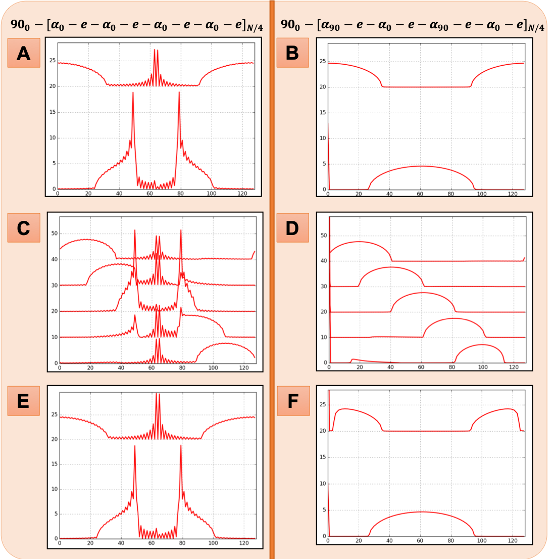
$$ 90_{\phi_{Ex}}-[\alpha_{\phi_{1}}-e-\alpha_{\phi_{2}}-e-\alpha_{\phi_{3}}-e-\alpha_{\phi_{4}}-e]_{N/4} $$
where $$$ \phi_{Ex} $$$ is the excitation phase; $$$ \alpha_{\phi_{i}} $$$ is the ith refocusing pulse with phase $$$ \phi_{i} $$$ and flip angle of α (α < 180° represents an imperfect |B1| field); ‘e’ represents the echo collected after each refocusing pulse; and N is the number of echoes collected (128 in this study). The refocusing pulses are alternately applied through different transmit coils for TRASE encoding.
Bloch equation6 simulations were performed for over 100 variants of this echo train pulse sequence using a maximum of 4 different refocusing pulse phases in cycled repetition. We investigated many different RF refocusing pulse phase combinations with the objective to find the best sequence performance, under conditions of |B1| inhomogeneity. We used a flip angle of α = 160° for an initial screening experiment aimed at understanding the performance of each sequence under B1 flip angle errors. Secondly, the point-spread-function (PSF) for the best-screened sequence was evaluated for a series of flip angles over the range $$$ 150^{\circ}<\alpha<200^{\circ} $$$.
Results
Figure 2 shows that the pulse sequence $$$ 90_{0}-[\alpha_{90}-e-\alpha_{0}-e-\alpha_{90}-e-\alpha_{0}-e]_{N/4} $$$ (represents a 90° phase difference between successive refocusing pulses first introduced by Maudsley7) results in a superior image reconstruction under |B1| errors than its counterpart. This is an improvement over the sequence which has all 0° pulse phases and produces destroyed TRASE object profiles at locations where only one component of Mxy is refocused. Figure 3 confirms, with stacked PSF plots, evenly spaced over the FOV, that this “90-0-90-0” sequence is effective for image reconstruction over ~90% of the TRASE FOV. This improves upon the previous sequence which generated ~75% usable field-of-view (FOV). With an increase in |B1| errors the usable FOV is observed to reduce and smear the PSF of certain points across the entire FOV which appear as mirror artifacts. Figure 4 provides an experimental validation of the simulation results.Conclusion
Our results show that when pulse phase patterns similar to that introduced by Maudsley7 are used in TRASE 1D MRI pulse sequences, image encoding is achievable over ~90% of the FOV for a reasonable variation in |B1| (± 15%) allowing the use of practical B1 transmit coil designs.Acknowledgements
We acknowledge the funding provided by the Canadian Space Agency (CSA )FAST - Zero-G MRI Project grant to Dr. Sarty (Principal Investigator) titled “Suborbital Development and Testing of a Space Flight Astronaut Magnetic Resonance Imager”.References
- J. C. Sharp and S. B. King, "MRI using radiofrequency magnetic field phase gradients," Magnetic resonance in medicine, vol. 63, pp. 151-161, 2010.
- G. Sarty, S. Kontulainen, A. Baxter-Jones, R. Pierson, K. Turek, A. Obenaus, et al., "Compact MRI for astronaut physiological research and medical diagnosis," in AIAA SPACE 2012 Conference & Exposition, 2012, p. 5240.
- Somaie Salajeghe, Paul Babyn, and Gordon E Sarty. “Composite pulses for RF phase encoded MRI: A simulation study”. In: Magnetic resonance imaging 36 (2017), pp. 40–48.
- Jason P Stockmann et al. “Transmit Array Spatial Encoding (TRASE) using broadband WURST pulses for RF spatial encoding in inhomogeneous B 0 fields”. In: Journal of Magnetic Resonance 268 (2016), pp. 36–48.
- S. Meiboom and D. Gill, "Modified spin‐echo method for measuring nuclear relaxation times," Review of scientific instruments, vol. 29, pp. 688-691, 1958.
- F. Bloch, "Nuclear induction," Physical review, vol. 70, p. 460, 1946.
- A. Maudsley, "Modified Carr-Purcell-Meiboom-Gill sequence for NMR fourier imaging applications," Journal of Magnetic Resonance (1969), vol. 69, pp. 488-491, 1986.
Figures