4631
3D Inner Volume Imaging with 3D Tailored Outer Volume Suppression RF pulses1fMRI Lab, Univ. of Michigan., Ann Arbor, MI, United States
Synopsis
3D inner-volume (IV) steady-state imaging is a candidate for, e.g., high-resolution BOLD fMRI, but it can be challenging to achieve sufficient outer-volume (OV) signal suppression. This is particularly true for 3D tailored RF pulses that excite an arbitrary 3D IV (e.g., a cylinder of finite height) thus enabling fast non-Cartesian readouts, as 3D IV pulses are more difficult to design than 2D tailored pulses. We propose to insert a 3D tailored OV suppression pulse to help suppress OV steady-state signal in 3D IV imaging sequences that use 3D tailored IV excitation pulses. We show that this strategy can substantially improve the IV signal profile for commonly used and emerging steady-state sequences such as spoiled gradient-echo (SPGR), balanced SSFP, and small-tip fast-recovery (STFR).
Introduction
3D (volumetric) steady-state imaging is an alternative to simultaneous multi-slice (SMS) imaging that is free from slice profile artifacts, is less vulnerable to spin-history effects due to, e.g., blood inflow, and may yield improved SNR. The latter can be exploited for high-resolution imaging, particularly if the imaging volume can be confined to a 3D inner-volume (IV) such that fast non-Cartesian (e.g., stack-of-spirals) readouts can be employed. Recently, Sun et al. proposed1 a 3D tailored RF pulse design algorithm that can yield 3D IV excitations using conventional single transmit coil MR systems. However, residual outer-volume (OV) excitation remains which is problematic in steady-state imaging due to the sub-linear dependence of the steady-state signal on flip angle (small flip angles in the OV are “amplified” relative to the IV signal).
In this work, we propose to insert a 3D tailored OV suppression pulse into three steady-state IV imaging sequences: SPGR, bSSFP, and STFR. We demonstrate that this strategy can suppress the OV signal significantly without disturbing the IV signal noticeably.
Methods:
Our proposed 3D tailored OV suppression RF pulse is designed using the algorithm described by Sun et al1:The excitation k-space trajectory is initialized with the “extended kT-points” method. This trajectory is then decomposed into a set of 2nd order B-splines, and the B-spline coefficients are then optimized using the interior point method, subject to gradient and slew rate hardware limits.
Figure 2a illustrates the target (design) 3D excitation, showing the IV, OV, transition, and background regions, respectively. The target pattern of the tailored OV pulse is essentially the inverse of that of the IV pulse: the IV excitation pulse aims to only excite IV spins, and the OV pulse aims to only excite OV spins. A transition region between the OV and IV region is prescribed as a “don’t care” region, i.e., it is excluded from the cost function in the pulse design procedure.
Figure 1 shows the timing diagrams for the three steady-state sequences in this study. For SPGR and STFR, the proposed 3D tailored OV suppression pulse is inserted after data readout and is followed by a spoiler gradient, after which the 3D IV excitation pulse starts the next TR. SPGR and STFR sequences were RF-spoiled (quadratic phase cycling). For bSSFP an additional spoiler gradient with opposite sign was inserted just before the OV pulse, balancing the overall gradient zeroth moment, and effectively acting to echo-shift the OV signal. For bSSFP, the IV pulse phase alternated between 0 and π, while the OV pulse had constant (zero) phase.
We conducted in vivo 3D IV imaging experiments in a healthy volunteer with SPGR, bSSFP and STFR sequences to evaluate the suppression efficacy of our proposed OV pulse. Acquisition parameters: TR=25.3 ms; TE=1.5 ms; nominal IV flip angle 14°; nominal OV flip angle 60°; image matrix size 120×120×40; FOV 24×24×20 cm³. Imaging experiments were performed on a GE Discovery MR750 3T scanner using 8-channel receive head coil.
Results
Figures 2c and 2d show the Bloch-simulated one-shot excitation pattern of the IV and OV pulses, respectively. As expected, the IV and OV pulses were able to respectively excite the regions of interest prescribed in Fig. 2a, while keeping other regions relatively untouched.
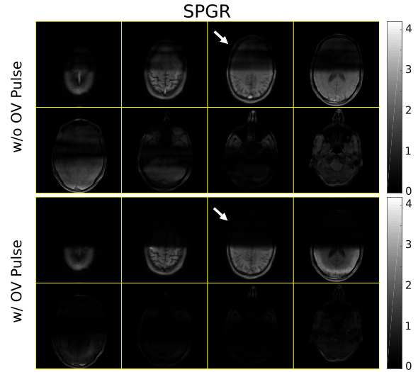
Figure 3 shows SPGR imaging results obtained both with and without the tailored OV suppression RF pulse. We observe good OV suppression with the tailored OV pulse, though some signal in inferior slices remain.
Similarly, Fig. 4 shows bSSFP imaging results. Again, the OV suppression pulse helps reduce the OV signal, although relatively large OV signal remains.
Figure 5 shows corresponding STFR results. We observe good OV suppression even without the proposed OV suppression pulse, due to intrinsic OV suppression from the tip-up pulse used in STFR2.
Conclusion and Discussion:
We have proposed an approach for OV signal suppression in 3D IV imaging based on saturating the OV steady-state signal using a 3D tailored RF pulse combined with spoiler/echo-shifting gradient(s). We demonstrated the efficacy of this approach for SPGR, bSSFP, and STFR sequences. In future work we will apply the ideas proposed here to high-resolution 3D IV fMRI.Acknowledgements
We wish to acknowledge the support of NIH Grants R01EB023618 and U01EB026977.References
- Sun, Hao, et al. "Joint design of excitation k-space trajectory and RF pulse for small-tip 3D tailored excitation in MRI." IEEE Transactions on Medical Imaging 2016; 35(2): 468-479.
- Sun, Hao, et al. "Rapid inner‐volume imaging in the steady‐state with 3D selective excitation and small‐tip fast recovery imaging." Magnetic Resonance in Medicine 2016; 76(4): 1217-1223.
Figures


(a) The whole FOV is divided into 4 regions. Background region is excluded in pulse design. Transition region is weighted as 0 in this experiment. IV and OV are the target region for the 3D IV and OV pulse, respectively.
(b) Reference image acquired with slab excitation. 8 out of 40 slices are shown.
(c,d) Bloch-simulated one-shot IV and OV excitations, respectively.