4630
PAREWISE: High-bandwidth, reduced-rephase, slice-selective excitation pulses for high-field spectroscopy1Canon Medical Research USA, Mayfield Village, OH, United States
Synopsis
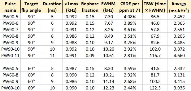
To meet the localization needs of high-field spectroscopy, new high-bandwidth computer-optimized RF excitation pulses have been generated, featuring phase modulation, t=0 points near the end of the pulse duration, B1 insensitivity over a ±15% range, and sharp excitation profiles. In the design process, a maximum amplitude of 1 kHz was imposed, and bandwidth was increased by stepping up the pulse length from 5 to 11 ms. Both 90° and 60° flip angles have been investigated thus far.
Introduction
One problem associated with high-field in vivo spectroscopy at 7T or 9.4T (or beyond!) is chemical shift displacement error (CSDE): the spatial displacement of the effective localized voxel for one metabolite vs. that of another. Because CSDE = (chemical shift difference) / (localization pulse bandwidth), higher pulse bandwidths (BW) are key to minimizing the problem. Switching from PRESS to semi-LASER circumvents the inherently limited BW of refocusing pulses by replacing them with pairs of adiabatic inversion pulses, but semi-LASER (as well as STEAM and simple slice-selective localization) still requires an excitation pulse. These are often purely amplitude-modulated (AM) sinc-like creations, but computer-optimized pulses incorporating phase modulation (PM) – or equivalently, frequency modulation (FM) – can provide a bandwidth boost1.
Here we explore just how wide and sharp a slice can be excited by creating a series of new Phase-modulated Asymmetric REduced-rephase WIder-Slice Excitation (PAREWISE) pulses.
Methods
Starting with an initial guess for the waveform, a conjugate-gradient algorithm was used to iteratively minimize a cost function that compared the actual slice profile at each step vs. a target profile2. For 90° excitation, MY = 1 was specified within the slice and MZ = 1 (and MX = MY = 0) beyond the slice, with a narrow transition zone of unspecified magnetization in-between. (More generally, for a desired flip angle θ, MY = sinθ and MZ = cosθ within the slice.) To provide a modest amount of B1 insensitivity, the pulse shape was also optimized at each step over a range of seven relative B1 levels from 85% to 115% of the nominally correct value. Additional terms were included in the cost function to penalize pulse jaggedness and overall pulse power. Each pulse was 500 points long.
Because pulse bandwidth can always be increased by cranking up the power, the maximum pulse amplitude ν1max was constrained to be less than 1.0 kHz. Longer pulse durations were used instead to increase the excitation BW. The pulse energy was thereby increased, but SAR is seldom a limiting factor at the long TR values used for in vivo spectroscopy. The pulse duration after the t=0 point ( = rephase fraction × pulse duration) was kept under 1 ms in all cases – in particular, to minimize spectral distortion in non-echo sequences that start sampling the excited FID as soon as possible.
Finally, an incremental approach was used to explore the realm of longer (and more complicated) pulse shapes: using (for example) a scaled version of a 7 ms waveform as the initial guess for an 8 ms pulse.
Results
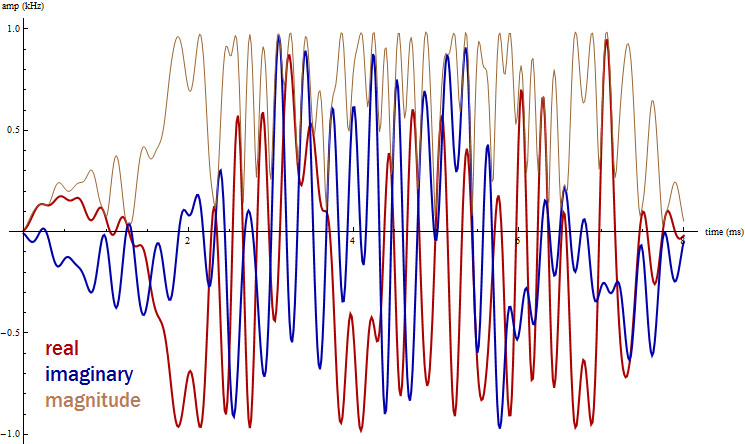
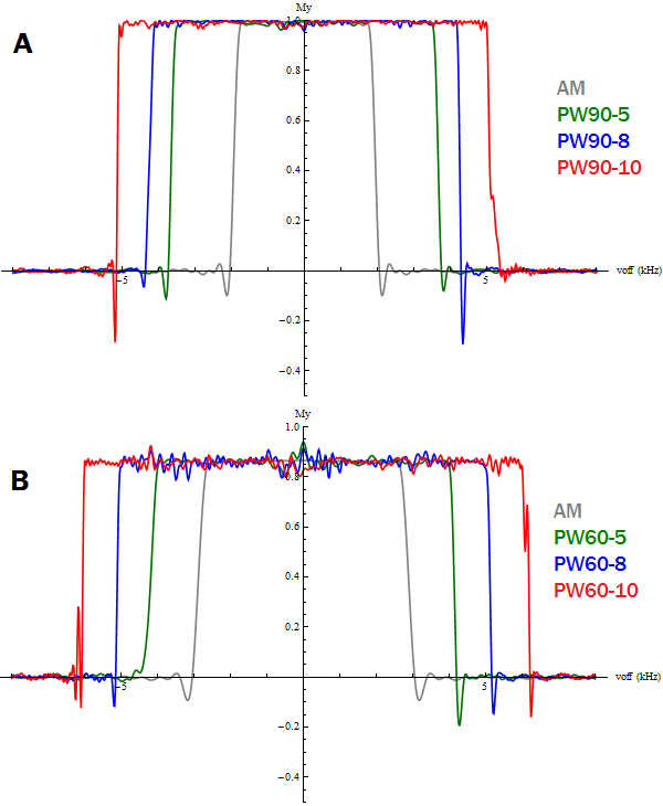
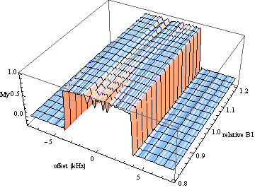
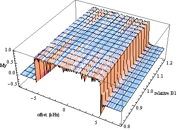
New 90° PAREWISE pulses with ν1max ≤ 1.0 kHz and durations from 5 to 11 ms were generated – usually with a limit of 2500 iterations. (Such calculations took ~6 hours on a laptop with a 2.9 GHz processor.) Even wider bandwidths were achieved for PAREWISE pulses at a lower target flip angle – specifically 60°. Details are found in Table 1. One resulting waveform, the 8 ms PW90-8 pulse, is displayed in Fig. 1. Excitation profiles for 5, 8, and 10 ms 90° pulses appear in Figure 2A, along with the profile of a conventional 3.6 ms asymmetric AM pulse with ν1max = 0.99 kHz. Corresponding profiles for 60° pulses appear in Figure 2B, plus that of a 2.4 ms AM pulse. Plotting MY as a function of both offset frequency and relative B1 level – as in Fig. 3 for the PW90-5 pulse and Fig. 4 for the PW90-10 pulse – reveals the built-in B1 insensitivity.Discussion
Unlike the case of AM pulses, the excitation profiles of asymmetric PM pulses are not necessarily symmetric with respect to offset frequency. The transition-zone divots in some of the profiles in Fig. 2 look a bit troublesome, but they correspond to only a tiny fraction of the overall profile width, and they likely can be minimized with further iterations that include small terms to control transition zone behavior.
These PAREWISE pulse shapes are the product of pure computer optimization rather than the application of pulse design principles – hence no insight into their operation is forthcoming. With 500×2 individual pulse amplitudes to vary, the multidimensional parameter terrain is so convoluted that the minima found are almost certainly local rather than global. Nonetheless, this pulse menagerie reveals what is possible in the quest for higher-bandwidth slice selection. Future optimizations will focus on the design of excitation pulses with even lower flip angles, for which even higher bandwidths should be possible.
Conclusion
For clean slice selection at high field, one should always pare wisely.Acknowledgements
No acknowledgement found.References
1. Henning A, Fuchs A, Murdoch JB, Boesiger P. Slice-selective FID acquisition, localized by outer volume suppression (FIDLOVS) for 1H-MRSI of the human brain at 7 T with minimal signal loss. NMR Biomed. 2009; 22: 683-696.
2. Murdoch JB, Lent AH, Kritzer MR. Computer-optimized narrowband pulses for multislice imaging. J Magn Reson. 1987; 74: 226-263.
Figures