4628
Spin Lock Adiabatic Correction (SLAC) of BIR4 pulses for increased B1-insensitivity at 7T1Dept. of Biomedical Engineering, University of Melbourne, Melbourne, Australia, 2Melbourne Brain Centre Imaging Unit, University of Melbourne, Melbourne, Australia, 3Department of Physical Sciences, Peter MacCallum Cancer Centre, Melbourne, Australia, 4Department of Medical Physics and Biomedical Engineering, Shiraz University of Medical Sciences, Shiraz, Iran (Islamic Republic of), 5Dept. of Medical Physics and Biomedical Engineering, Shiraz University of Medical Sciences, Shiraz, Iran (Islamic Republic of), 6Dept. of Electrical and Electronic Engineering, University of Melbourne, Melbourne, Australia
Synopsis
Inhomogeneous B1 excitation impedes image quality, particularly at high field. Adiabatic pulse modulation ameliorates this effect, however super-adiabatic properties can be exploited to further improve performance. Spin Lock Adiabatic Correction (SLAC) pulses can be applied to any adiabatic pulse shape, through reduction of flip angle inaccuracies induced by B1 variability. In this work, SLAC is derived for BIR4 pulse shapes, and the superior performance of SLAC-BIR4 is demonstrated in both simulation and phantom experiments at 7T. The SLAC procedure is an attractive analytical alternative to numerical optimisation of adiabatic pulses.
Introduction
In ultra-high field MRI systems, the $$$B_1$$$ fields generated by single channel transmit coils are spatially inhomogeneous and result in substantial flip-angle variation when using conventional RF pulses1. Mitigating the effects of this $$$B_1$$$ inhomogeneity using RF pulse design has been a major area of work for decades, resulting in classes of pulse design such as adiabatic pulses2 and composite pulses3. Extension beyond the traditional, mathematically elegant adiabatic pulse shapes has occurred via numerical optimisation (NOM) procedures of temporal envelope modulation4,5. Spin Lock Adiabatic Correction (SLAC) pulses6 are a recent class of pulses that can deliver improved $$$B_1$$$ insensitivity through analytically-derived amplitude and phase modulation of adiabatic pulses. In this work, we demonstrate that SLAC pulses generated from BIR4 pulses7 outperform standard BIR4 design, in numerical simulation and in acquisition of experimental data at 7T.Theory
Consider an arbitrary adiabatic pulse defined by amplitude and phase functions, $$$B_{1,Ad}(t)$$$ and $$$\phi(t)$$$, respectively, with effective field, $$$\tilde{B}_{eff}$$$ and flip angle, $$$\alpha$$$ (Fig.1a). A second rotating frame aligned with $$$\tilde{B}_{eff}$$$ (Fig.1b) defines a cone with axis $$$\tilde{E} = \tilde{B}_{eff} + B_\perp$$$, where $$$B_\perp = \frac{d\alpha}{dt}$$$, and aperture, $$$\epsilon$$$. Cone aperture relates to flip angle accuracy.
The SLAC procedure reduces the cone aperture through introduction of an opposing spin lock component. SLAC is defined by the complex envelope function,
$$B_1(t) = \left(B_{1,Ad}(t) + i B_{1,SL}(t)\right)e^{i\phi (t)},$$
where $$$B_{1,SL}(t) = - \frac{1}{\gamma} \frac{d\alpha}{dt}$$$.
The effect of $$$B_{1,SL}$$$ is to null $$$B_\perp$$$. This occurs at the expense of increased $$$B_1$$$
amplitude. As shown below, the power can be matched to the adiabatic pulse power, however a small residual $$$B_\perp$$$ will remain unsupressed.
Method
To demonstrate that SLAC is applicable to arbitrary flip angles, it has been applied to a 45$$$^\circ$$$ 10ms tanh/tan BIR4 pulse with $$$\zeta=20$$$, $$$\kappa=\tan^{-1}(20)$$$, $$$\Delta\omega_{max}=$$$ 5kHz7. As the power deposited by the analytically derived SLAC envelope is greater than for the BIR4, we implemented a SLAC envelope rescaled equal to BIR4 in terms of power deposition (Fig.2).
Simulation:
The Bloch equations were numerically simulated (MATLAB) to predict the transverse magnetisation following 45$$$^\circ$$$ BIR4 and SLAC-BIR4 pulses as a function of pulse duration and reference $$$\omega_1$$$ amplitude, defined as BIR4 $$$\omega_{1,max}$$$.
Experiment:
Data was acquired of a spherical phantom at 7T (Siemens Healthineers, Erlangen, Germany) using a single-channel TX-RX volume coil (QED, USA). Non-selective excitation pulses were followed by a custom-built 3D Cartesian GRE readout (TR=5000ms, TE=10ms, Bandwidth = 260Hz/px, Matrix size=256x128x64, FOV=200mm isotropic). An image volume was obtained for each of the following pulses: 45$$$^\circ$$$ flip angle, lengths of 0.5ms (block) and 10ms (BIR4 and SLAC-BIR4).
Results and Discussion
Simulation:
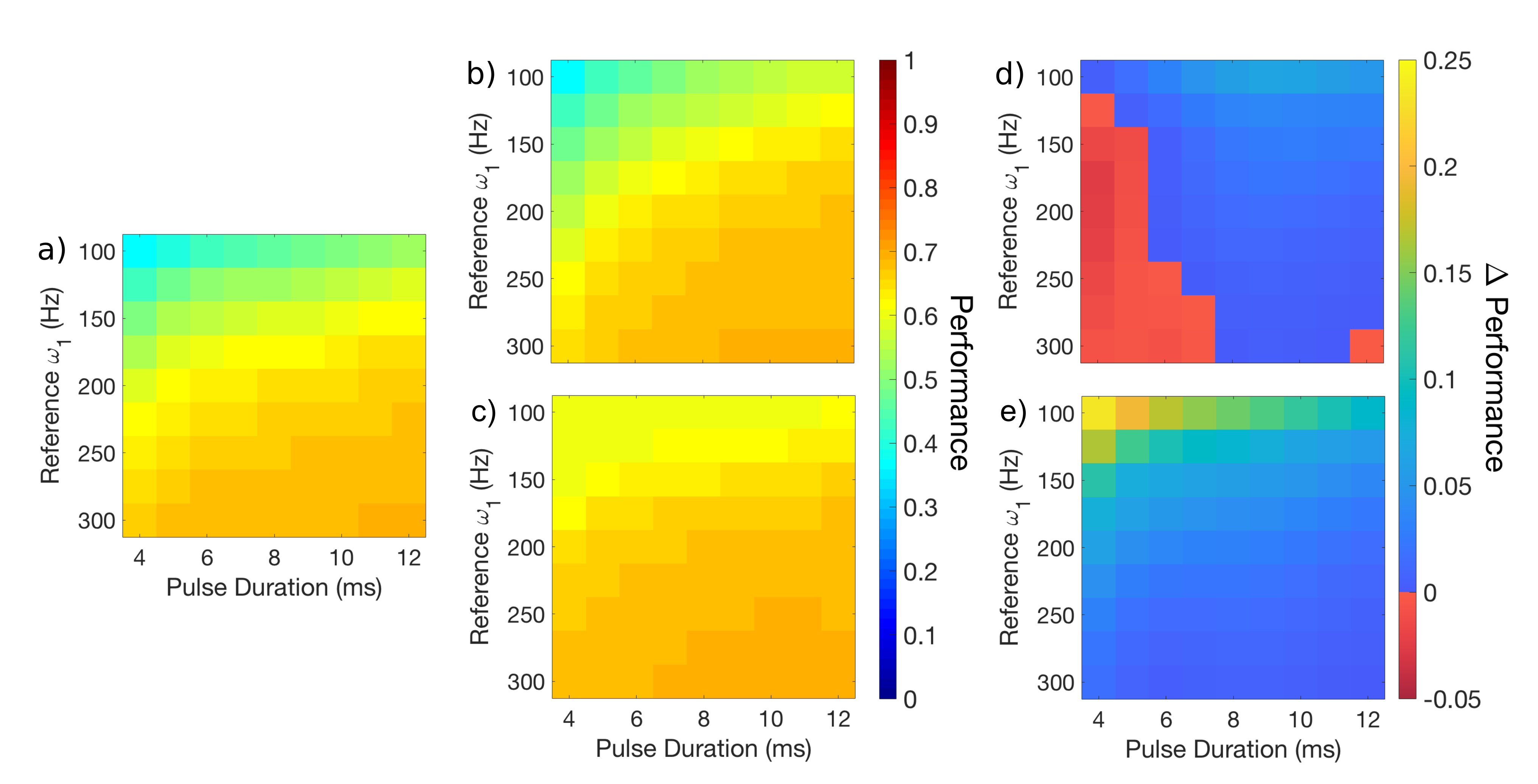
The comparative performance of the three pulses types, BIR4 (Fig.3a), power-matched SLAC-BIR4 (Fig.3b) and unmatched SLAC-BIR4 (Fig.3c), demonstrates the expected effects of longer and higher power pulses. More interesting, however, is that for most pulse durations and reference $$$\omega_1$$$ amplitudes, the power-matched SLAC-BIR4 outperforms the standard BIR4 (Fig.3d). The high power, low duration region in which BIR4 is better is a region in which a block pulse will outperform adiabatic excitation. For completeness, as expected, the mean transverse magnetisation following an unmatched SLAC-BIR4 exceeds the BIR4 everywhere (Fig.3e).
The resultant transverse magnetisation across $$$B_1$$$ strengths for 10ms, 45$$$^\circ$$$ BIR4 and SLAC-BIR4 pulses is depicted in Fig.4. The power-matched SLAC-BIR4 increases the signal for low $$$B_1$$$ regions compared with a standard BIR4, while all perform equally (except the block pulse) for higher $$$B_1$$$ powers.
Experiment:
Block pulse excitation (Fig.5a) shows higher intensity in the high $$$B_1$$$ regions and lower intensity in the low $$$B_1$$$ regions than BIR4 (Fig.5b) and SLAC-BIR4 (Fig.5c). Areas of low $$$B_1$$$ in the SLAC-BIR4 image contain on the order of 10% more signal than the BIR4 image (Fig.5d), while in areas of high $$$B_1$$$ strength they are equivalent. Both of these observations agree well with simulation predictions, that SLAC reduces the sensitivity to B1 inhomogeneity without a concomitant increase in power deposition.
Conclusion
It has been validated that SLAC has the capacity to reduce flip angle inhomogeneity at 7T by minimising the deviation of the trajectory of magnetisation from $$$\tilde{B}_{eff}$$$ with no increase in energy deposition. The SLAC procedure is applicable to any adiabatic pulse form; here its performance was demonstrated for an arbitrary 45$$$^\circ$$$ flip angle compared to the BIR4 adiabatic pulse. Work is ongoing to determine the efficacy of SLAC pulses for optimised adiabatic inversion.Acknowledgements
We acknowledge the facilities, and the scientific and technical assistance of the Australian National Imaging Facility at the Melbourne Brain Centre Imaging Unit. The Australian National Imaging Facility is funded by the Australian Government NCRIS program.References
1. Vaughan JT, Garwood M, Collins CM, et al. 7T vs. 4T: RF power, homogeneity, and signal‐to‐noise comparison in head images. MRM 2001;46(1):24-30.
2. Garwood M, DelaBarre L. The return of the frequency sweep: Designing adiabatic pulses for contemporary NMR. JMR 2001;153(2):155-177.
3. Levitt MH, Composite Pulses. Progress in Nuclear Magnetic Resonance Spectroscopy. 1986;18:61-122.
4. Ugurbil K, Garwood M, Bendall MR. Amplitude- and frequency-modulated pulses to achieve 90° plane rotations with inhomogeneous B1 fields. JMR 1987;72:177-85.
5. Ugurbil K, Garwood M, Rath AR, Bendall MR. Amplitude- and frequency/phase-modulated refocusing pulses that induce plane rotations even in the presence of inhomogeneous B1 fields. JMR 1988 Jul 1;78(3):472-97.
6. Green EM, Korte JC, Tahayori B, Farrell PM, Johnston LA. Spin Lock Adiabatic Correction (SLAC) Excitation. In Proceedings of the 26th Annual Meeting of the ISMRM, Paris, France. 2018.
7. Garwood M, Ke Y. Symmetric pulses to induce arbitrary flip angles with compensation for RF inhomogeneity and resonance offsets. JMR 1991;94(3):511-525.
Figures