4625
RF pulse design via time optimal control for combined excitation, refocusing and inversion1Institute of Medical Engineering, Graz University of Technology, Graz, Austria, 2Institute for Mathematics and Scientific Computing, University of Graz, Graz, Austria
Synopsis
This work demonstrates a constrained joint design of minimum duration RF pulse and slice selective gradient waveforms for combined SMS excitation, refocusing and inversion scenarios. A hybrid trust-region semismooth Newton/quasi-Newton method with exact derivatives via adjoint calculus is used to solve the time optimal problem on fine spatial and temporal grids. Specific hardware and safety constraints, including maximal RF, slice selective gradient, slew rate amplitudes as well as global SAR estimates, guarantee practical applicability. High-resolution GRE, crushed SE and inversion recovery GRE slice profile measurements on a 3T MR system validate the numerical results.
Target audience:
Researchers working in the field of RF pulse design and SMS imaging.Purpose:
Simultaneous Multislice (SMS) imaging is often limited by long RF pulse durations which result from hardware limitations and the demand for many accurate slices1. The overall pulse duration and RF energy requirements can be addressed with various methods1,2,3 including time optimal joint design of RF pulse and slice selective gradient shape4,5. Since the resulting Gs amplitudes are allowed to vary heavily, a refined gradient system model based on the gradient impulse response function was introduced to correct for potential gradient system imperfections6. In this work, we extend the optimization framework5 to the design of combined time optimal SMS excitation, refocusing and inversion scenarios.Theory:
The time optimal control framework for the constraint joint design of RF and slice selective gradient shape is formulated in the Bloch spin domain in terms of Cayley-Klein parameters for different RF pulse types7 including excitation $$$(2ab^*)$$$, inversion $$$(1-2|b|^2)$$$ and crushed refocusing $$$(|b|^2)$$$. In addition to the magnitude slice profile evaluation, the phase angle of the slice profile can be added for excitation or refocusing scenarios. Maximal amplitude values for RF and Gs slew rate are included as pointwise hard constraints. The time optimal problem is solved with a hybrid trust-region semismooth Newton/quasi-Newton method with exact derivatives via adjoint calculus4,5.Methods:
The proposed algorithm is implemented in MATLAB (The MathWorks, Inc, Natick, USA) and the calculations are done in parallel (OpenMP). The iterative optimization starts with a PINS8 RF and slice selective gradient shape based on a SLR7 sub-pulse with a flip angle of 90° for excitation and 180° for refocusing and inversion. The optimization framework is tested on 39 different examples covering a wide range of parameters (multiband-factor MB=2-8, slice thickness THK=1-5mm and time-bandwidth-product TBWP=2-8). The spatial domain is fixed to 120mm with varying spatial discretization points (961-4801) and a fixed temporal discretization of 10µs with varying initial pulse durations (6.82ms-32.8ms). The amplitude constraints were fixed to RFmax=12.5µT, Gsmax=30mT/m and slew ratemax=180T/m/s, respectively. The slice profile constraints are set to a maximum magnitude error of 1% and an optional maximum phase deviation of 0.025rad. The optimized RF and slice selective gradient shapes are implemented on a 3T MR scanner (Magnetom Skyra, Siemens Healthcare, Erlangen, Germany). High-resolution GRE, SE and inversion recovery GRE scans (TR/TE=100-500ms/10-20ms, FOV=125x125mm, matrix=640×640) of a homogeneous cylinder (T1/T2≈102/77ms) with phase encoding in slice-direction validate the numerical results.Results and Discussion:
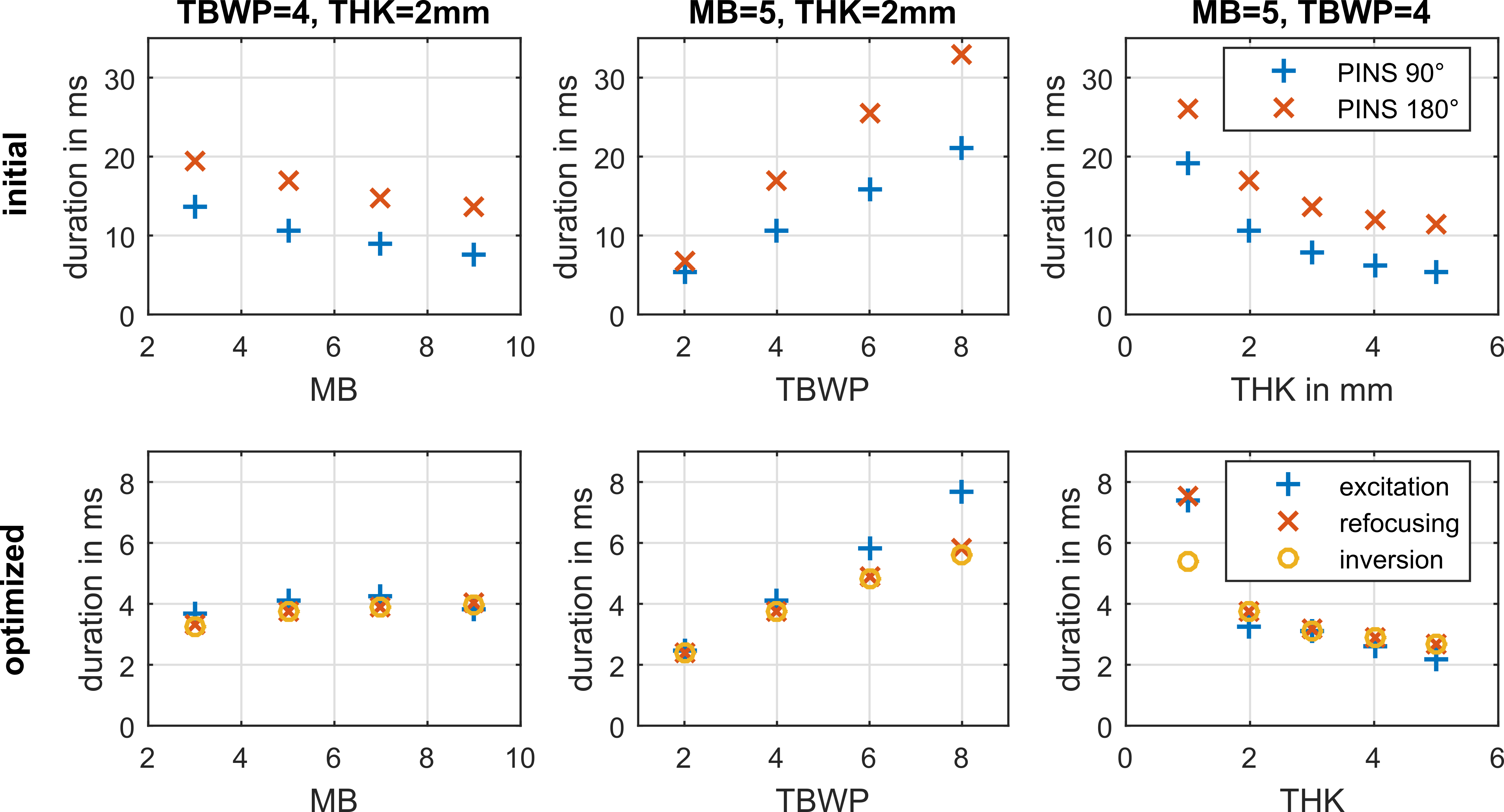
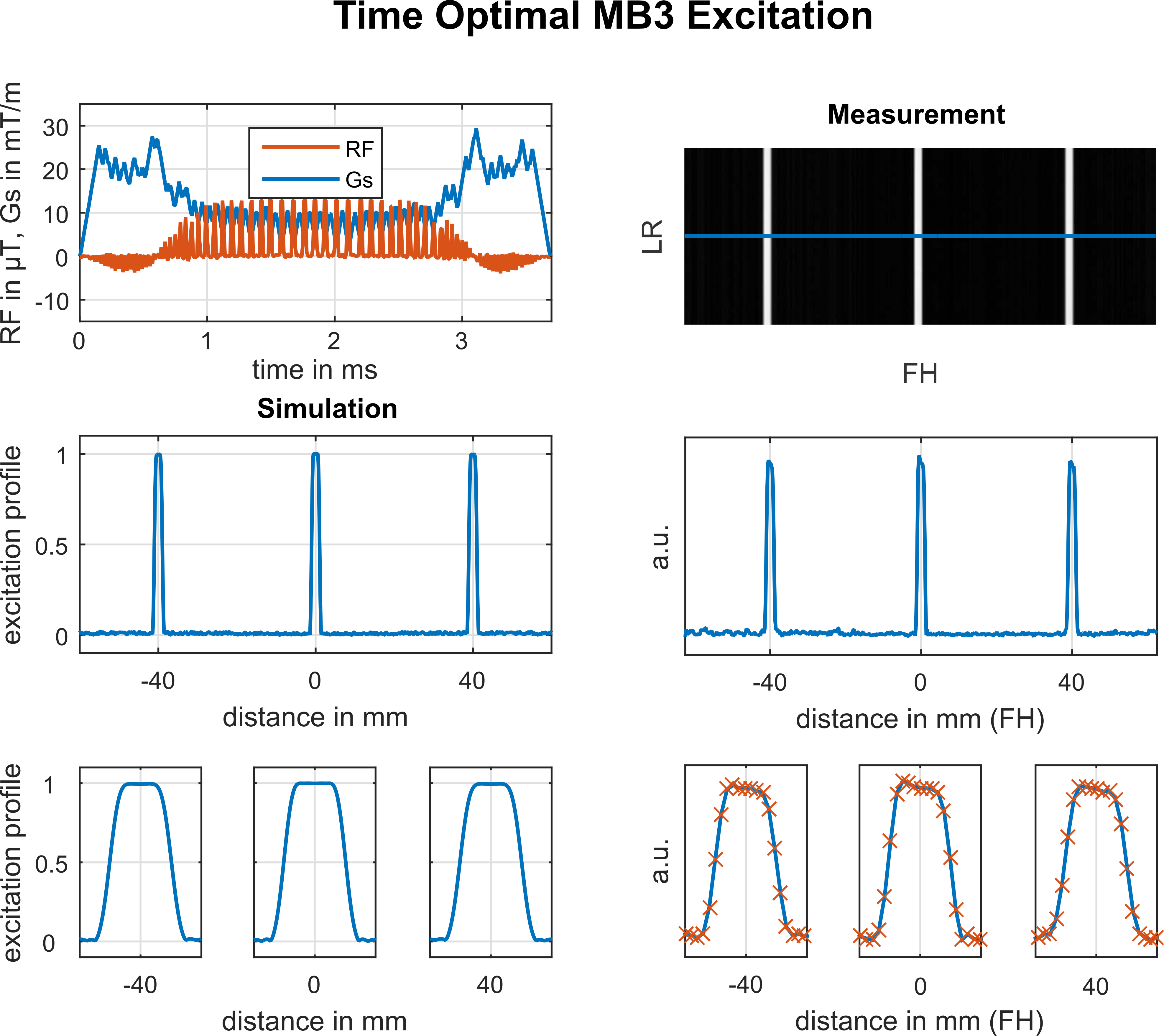
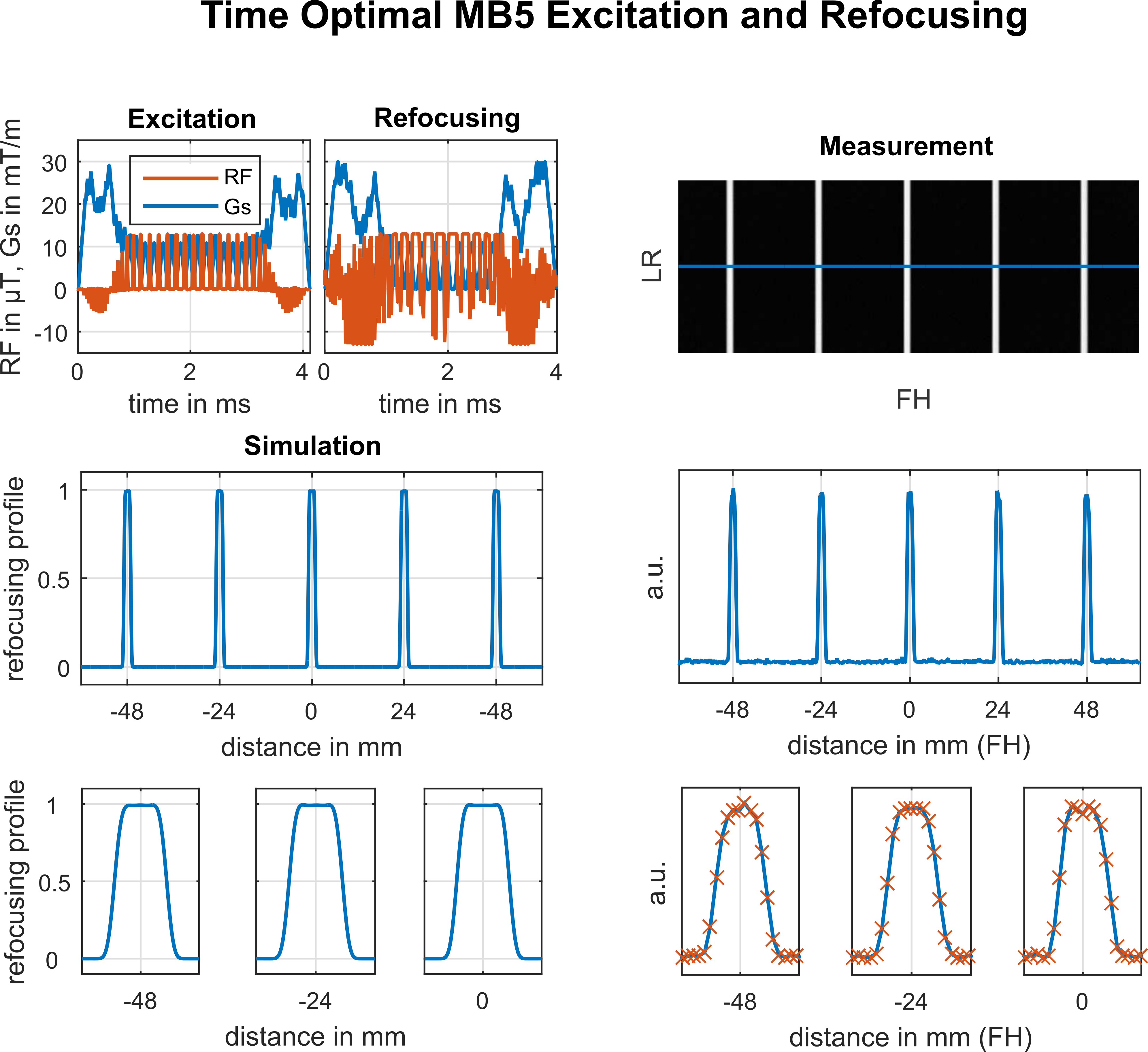
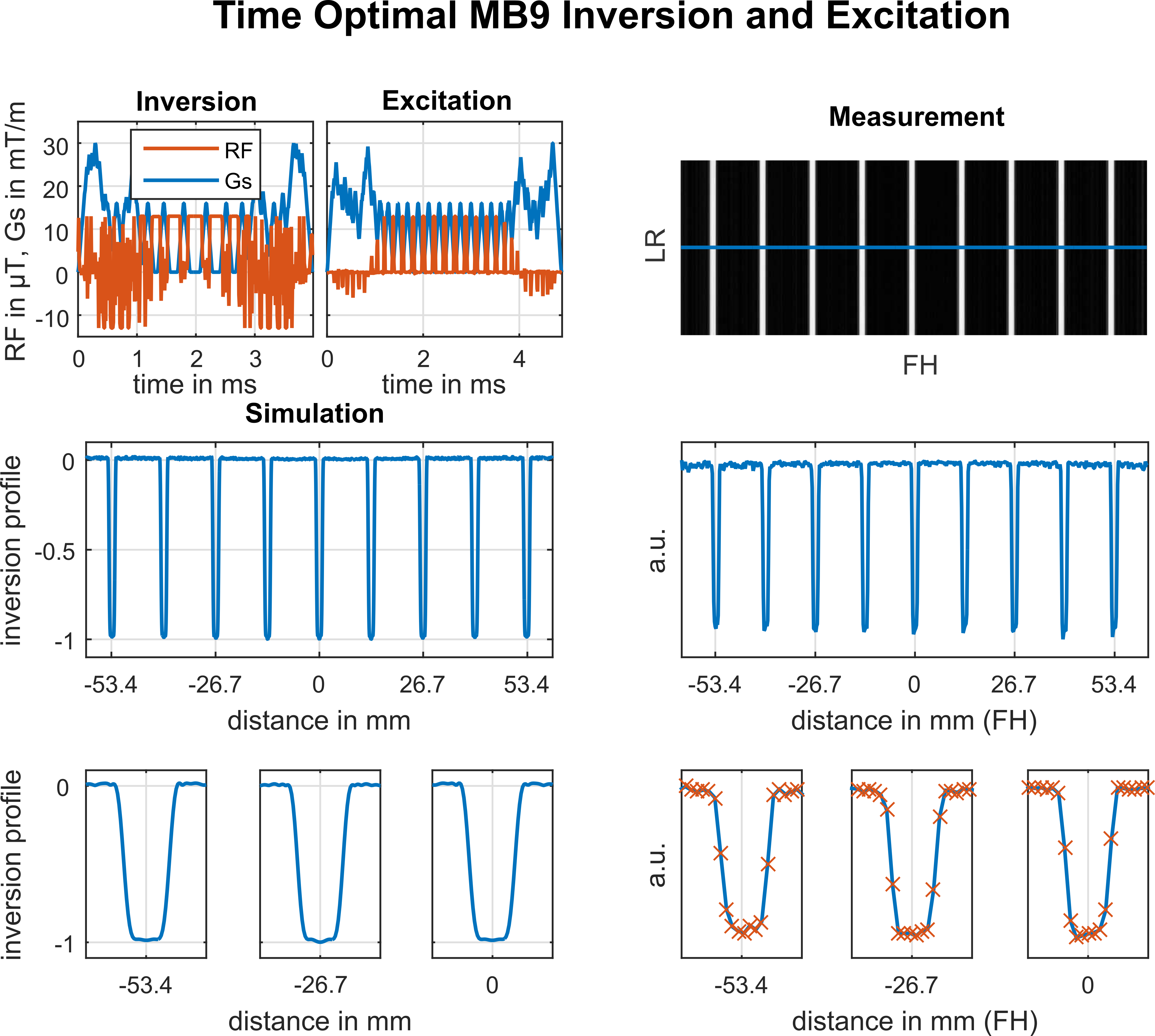
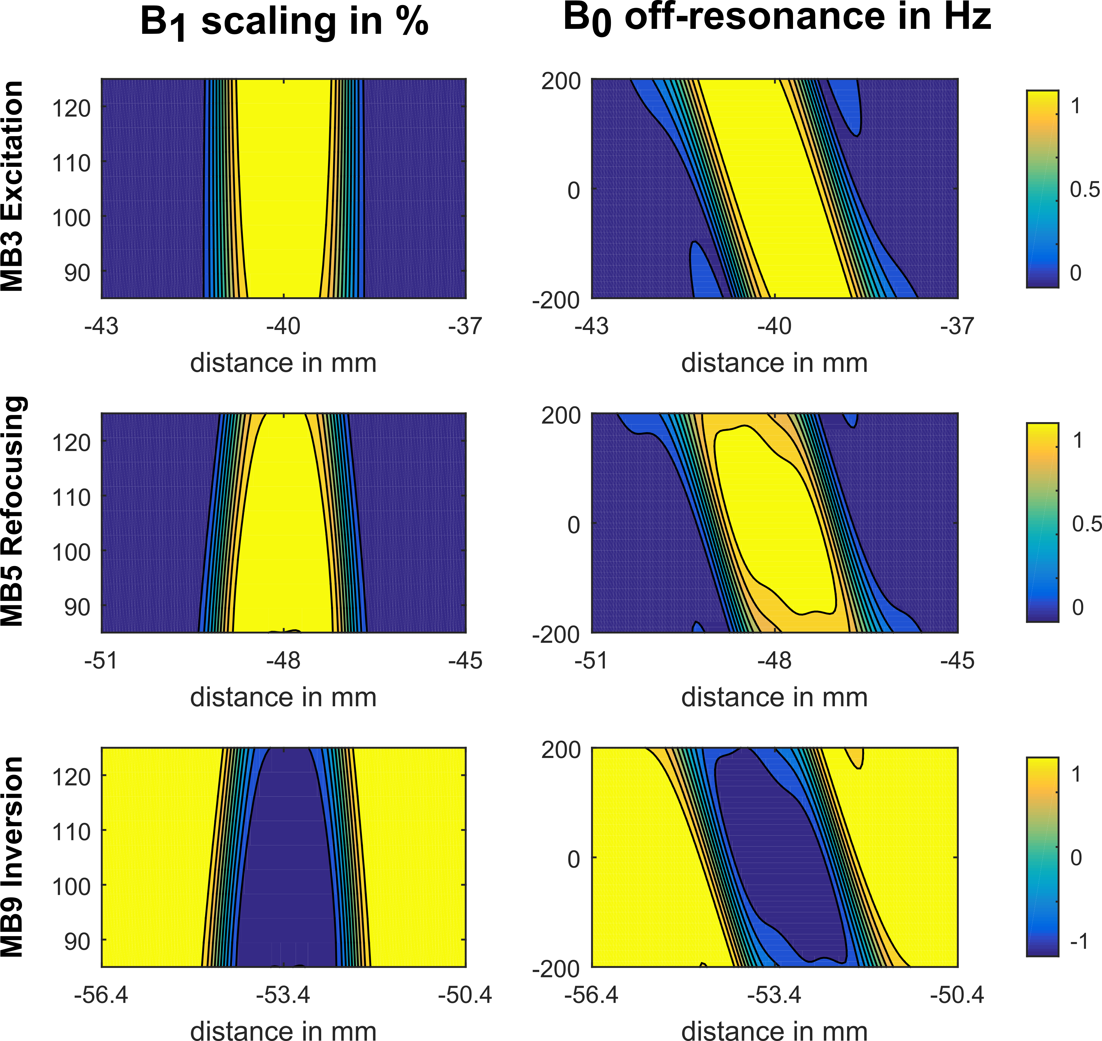
Figure 1 shows the pulse durations of the used PINS initializations (row 1) together with 39 time optimal results (row 2) for varying MB factor (3-9), TBWP (2-8) and THK (1-5mm). The average durations are heavily reduced across all optimized results from initial 11.1ms to 4.23ms (excitation), 17.56ms to 3.99ms (refocusing) and to 3.81ms (inversion). The achieved reduction therein results from an exploitation of prescribed inequality constraints such as maximal RF, slice selective gradient (Gs) and slew rate amplitudes as well as slice profile magnitude and phase constraints and guarantee practical applicability of the optimized waveforms. Contrary to the initial expectations, the pulse duration of the optimized excitation pulses is close to the optimized 180° examples where a more sensitive out-of-slice error limited a further time reduction. Figure 2 shows one representative optimized excitation example (MB=3, THK=2mm, TBWP=4). Depicted are the simulated excitation and the measured spoiled GRE slice profile. A standard trapezoidal refocusing gradient refocused the linear phase angle of the excitation profile (not shown). Figure 3 shows one optimized refocusing example (MB=5, THK=2mm, TBWP=4) with a matching excitation pulse and compares the Bloch simulation to the corresponding crushed SE measurement. Figure 4 shows one optimized inversion example (MB=9, THK=2mm, TBWP=4) with a matching excitation pulse and compares the numerical with the experimental results. All measurements reproduce the Bloch simulations and demonstrate the applicability of the optimized waveforms. Figure 5 shows the simulated slice profiles for a B1 variation of 85-125% and a B0 offset range of ±200Hz for the previously shown results. In particular, the results show an increased robustness of the optimized excitation pulse (row 1) compared to the similar refocusing and inversion efficiency.Conclusion:
The
proposed framework designs minimum-duration RF and Gs shapes
for the most commonly used RF pulse types in the presence of physical and technical
constraints. The optimized results can be combined for
time optimal excitation, refocusing or inversion purposes. The proposed framework serves as a basis for a
direct design of pulse series such as steady state or magnetization preparation
sequences to further reduce effective echo times.Acknowledgements
Supported by the Austrian Science Fund (FWF): SFB F32‐N18 and BioTechMed-GrazReferences
1) Barth M, Breuer F, Koopmans PJ, Norris DG and Poser BA. Simultaneous multislice (SMS) imaging techniques. Magn. Reson. Med. 75(1):63–81, 2016.
2) Grissom WA, Setsompop K, Hurley SA, Tsao J, Velikina JV and Samsonov AA. Advancing RF pulse design using an open-competition format: Report from the 2015 ISMRM challenge. Magn. Reson. Med. 78(4):1352–1361, 2016.
3) S. Abo Seada, A.N. Price, T. Schneider, J.V. Hajnal and S.J. Malik. Multiband RF pulse design for realistic gradient performance. Magn. Reson. Med. Early View, 2018.
4) A. Rund, C.S. Aigner, K. Kunisch, and R. Stollberger. Magnetic Resonance RF pulse design by optimal control with physical constraints. IEEE Trans. Med. Imaging, 37(2):461-472, 2018.
5) A. Rund, C.S. Aigner, K. Kunisch, and R. Stollberger. Simultaneous multislice refocusing via time optimal control. Magn. Reson. Med. 80(4):1416-1428, 2018.
6) C.S. Aigner, A. Rund, S. Abo Seada, S. Malik, J.V. Hajnal, K. Kunisch and R. Stollberger. Time-optimal control based RF pulse design under gradient imperfections. Proc. Intl. Soc. Mag. Reson. Med. 26, 0209, Paris, France, 2018.
7) Pauly J, Le Roux P, Nishimura D, and Macovski A. Parameter relations for the Shinnar-Le Roux selective excitation pulse design algorithm. IEEE Trans. Med. Imaging 10(1), 1991.
8) Norris DG, Koopmans PJ, Boyacioglu R and Barth M. Power Independent of Number of Slices (PINS) radiofrequency pulses for low-power simultaneous multislice excitation. Magn. Reson. Med. 66(5):1234–1240, 2011.
Figures