4622
Improved Accuracy of FLASH-based B1+ Mapping by Optimization of the Fourier Encoding Matrix1Centre for Functional and Metabolic Mapping, University of Western Ontario, London, ON, Canada, 2Department of Medical Biophysics, University of Western Ontario, London, ON, Canada
Synopsis
FLASH-B1 mapping with a Fourier-encoding scheme works only for a limited range of flip-angles due to pronounced saturation effects that occur for short TR. The transmit voltage can be adjusted to satisfy this requirement in problematic Fourier combinations that have high dynamic range. However, this results in an unnecessary reduction of the dynamic range in combinations that are already within the accepted range. This study addresses this problem by optimizing the Fourier encoding matrix such that the flip-angle is reduced only in regions of high flip-angle in the problematic combinations.
Introduction
Parallel-transmit systems bring in the possibility of mitigating $$$B_1^+$$$ inhomogeneity by RF shimming1 or RF pulse design2. The efficacy of both strategies depends on the accuracy of $$$B_1^+$$$ maps, which is challenged by the high dynamic range of $$$B_1^+$$$ for a single transmit element. This is ameliorated by mapping $$$B_1^+$$$ for linear combinations of transmit channels, i.e. the “channel-$$$B_1^+$$$” information is encoded in the “combination-$$$B_1^+$$$”3,4. The Fourier encoding scheme offers a significant advantage over other schemes since it is less susceptible to RF destructive interferences, an effect that is pronounced at high magnetic fields5.
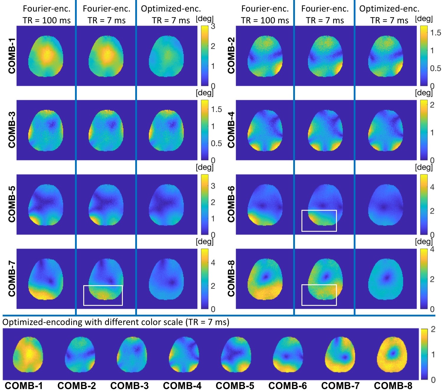
Regardless of which encoding scheme is used, the conventional $$$B_1^+$$$ mapping techniques are lengthy and often impractical considering that $$$B_1^+$$$ must be mapped for each combination. To combat this, it has been proposed to acquire $$$|B_1^+|$$$ for only one combination (default (CP)-mode) which is complemented by low-flip-angle GRE images for all combinations (see Figure 1 for details)6,7. This technique, referred here to as “FLASH-$$$B_1^+$$$ mapping”, assumes GRE images to be linearly proportional to $$$|B_1^+|$$$ provided that the flip-angle (FA) is sufficiently small to neglect saturation effects. For example, the maximum allowed FA ($$$maxFA$$$) is about 2° in the human brain with a TR of 7 ms (Figure 1). Therefore, in any regions where FA exceeds 2°, combination-$$$B_1^+$$$ is underestimated (Figure 2). The trivial solution to this problem is to adjust the transmit voltage such that $$$FA<maxFA$$$ in all regions and combinations. However, this results in an unnecessary reduction of the dynamic range in combinations that already below the $$$maxFA$$$ and thereby the accuracy is compromised.
In this study, we address this problem by using an iterative method to modify the Fourier encoding matrix. The weights of the combinations for which $$$FA>maxFA$$$ are updated such that only the local regions of high FA are eliminated, while for other combinations, the weights are kept the same.
Methods
Iterative Method to Optimize Fourier Encoding Matrix:
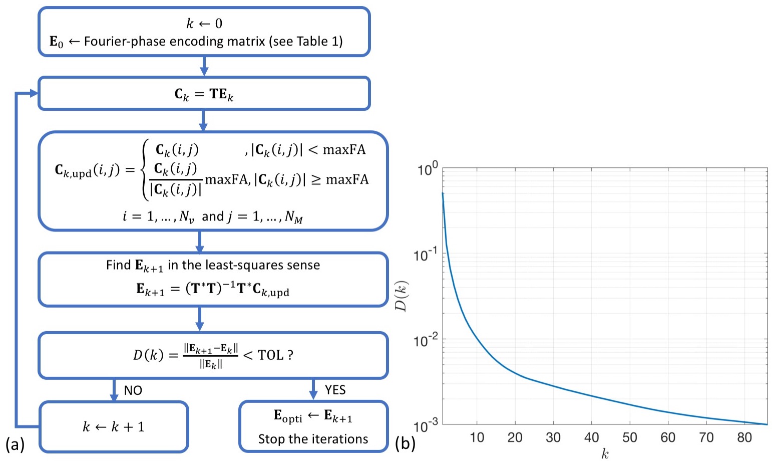
The relation between the channel-$$$B_1^+$$$ and the combination-$$$B_1^+$$$ can be written in the matrix form as $$\mathbf{T}_{N_v\times{N_c}}\mathbf{E}_{N_c\times{N_m}}=\mathbf{C}_{N_v\times{N_m}}$$ where $$$\mathbf{T}$$$ contains the complex channel-$$$B_1^+$$$ for each of the $$$N_v$$$ voxels and $$$N_c=8$$$ channels, $$$\mathbf{C}$$$ contains the complex combination-$$$B_1^+$$$ for each of the $$$N_v$$$ voxels and $$$N_m=8$$$ combinations, and $$$\mathbf{E}$$$ is the encoding matrix. In $$$\mathbf{T}$$$ and $$$\mathbf{C}$$$ matrices, the magnitude of $$$B_1^+$$$ was represented by the corresponding flip-angle. The true transmit channel-$$$B_1^+$$$, $$$\mathbf{T}$$$, was obtained using FLASH-$$$B_1^+$$$ mapping with a long TR of 100 ms to reduce saturation effects. The aim of the iterative algorithm is to find $$$\mathbf{E}$$$ such that all elements of $$$\mathbf{E}$$$ are below $$$maxFA$$$ of 2°. This is done once and the optimized encoding matrix ($$$\mathbf{E}_{opti}$$$) is used in subsequent experiments with a short TR of 7 ms. The steps of the algorithm are summarized in Figure 3.
Experimental Methods:
Measurements were performed on a Siemens 7 T head-only MRI scanner (Erlangen, Germany) using an RF coil with 8 transmit and 32 receive channels8. Axial 2D brain images were acquired from a single slice using FLASH (FOV 220x220 mm, image matrix size 128x128, slice thickness 5 mm, TE 1.95 ms, TR 7 or 100 ms). The $$$|B_1^+|$$$-map for the first combination was acquired using Bloch-Siegert-shift-based $$$B_1^+$$$ mapping technique (TE/TR 11/100 ms, FA 25°, Fermi-shaped off-resonance RF pulse (frequency shift 4 kHz, duration 8 ms, nominal peak-$$$|B_1^+|$$$ 5.6 µT)).
Results
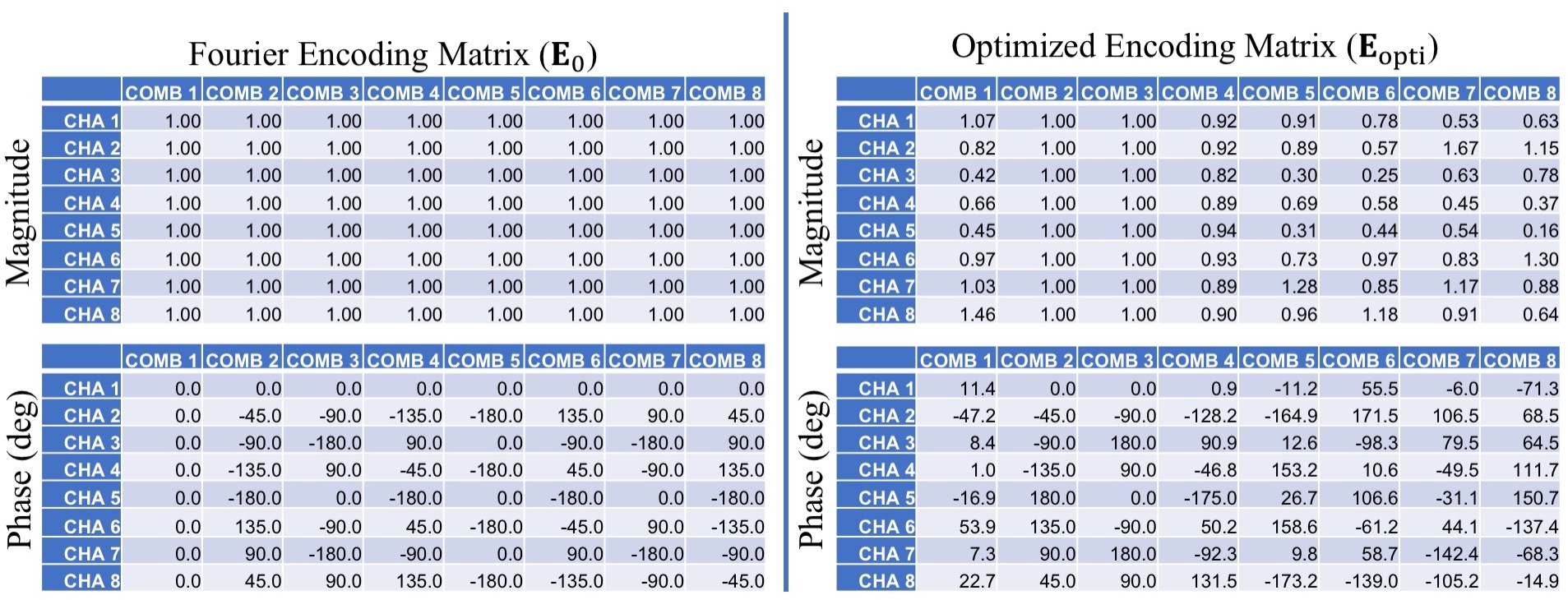
When TR=7 ms, $$$B_1^+$$$ was underestimated by up to 25% for some Fourier combinations that have $$$FA>maxFA$$$ (Figure 2). This was also reflected as an underestimation in the channel-$$$B_1^+$$$ (Figure 4). Using the optimized encoding matrix, the maximum FA of the combination-$$$B_1^+$$$ was lowered below $$$maxFA$$$ where needed (Figure 2). Consequently, the corresponding channel-$$$B_1^+$$$ showed no signs of underestimation (Figure 4). Note that the weights were updated only for combinations that have high FAs (Table 1). With a condition number of 3.9, the inverse of $$$\mathbf{E}_{opti}$$$ is still well-defined.Discussion and Conclusion
This study shows that the FLASH-$$$B_1^+$$$ mapping with Fourier-encoding scheme can fail for short TR values. With the optimization of the encoding matrix, the combination-$$$B_1^+$$$ was maintained within the accepted limits without globally reducing the transmit voltage.
The encoding matrix was optimized using true $$$B_1^+$$$ maps that were obtained from a single subject. However, $$$B_1^+$$$ field distribution in the brain varies for each individual, and $$$\mathbf{E}_{opti}$$$ for one individual might cause errors for others. To overcome this challenge, we plan to acquire true $$$B_1^+$$$ maps from multiple subjects and apply the optimization algorithm by vertically concatenating $$$\mathbf{T}$$$ matrices of each subject.
Acknowledgements
This work was supported by The Natural Sciences and Engineering Research Council of Canada (NSERC) Discovery Grant to Ravi Menon.References
1. Mao W, Smith MB, Collins CM. Exploring the limits of RF shimming for high-field MRI of the human head. Magn. Reson. Med. 2006;56:918–922.
2. Grissom W, Yip C, Zhang Z, Stenger VA, Fessler JA, Noll DC. Spatial domain method for the design of RF pulses in multicoil parallel excitation. Magn. Reson. Med. 2006;56:620–9.
3. Nehrke K, Börnert P. Improved B1-Mapping for Multi RF Transmit Systems. In: Proceedings of the 16th Annual Meeting of ISMRM, Toronto, Ontario, Canada. ; 2008. p. 353.
4. Brunner DO, Pruessmann KP. B1+ interferometry for the calibration of RF transmitter arrays. Magn. Reson. Med. 2009;61:1480–1488.
5. Tse DHY, Poole MS, Magill AW, Felder J, Brenner D, Jon Shah N. Encoding methods for B1+ mapping in parallel transmit systems at ultra high field. J. Magn. Reson. 2014;245:125–132.
6. Van De Moortele P-F, Snyder C, Delabarre L, Adriany G, Vaughan T, Ugurbil K. Calibration Tools for RF Shim at Very High Field with Multiple Element RF Coils: From Ultra Fast Local Relative Phase to Absolute Magnitude B1+ Mapping. In: Proceedings of the 15th Annual Meeting of ISMRM, Berlin, Germany. ; 2007. p. 1676.
7. Setsompop K, Alagappan V, Gagoski B, et al. Slice-selective RF pulses for in vivo B1+inhomogeneity mitigation at 7 Tesla using parallel RF excitation with a 16-element coil. Magn. Reson. Med. 2008;60:1422–1432.
8. Gilbert KM, Gati JS, Kho E, Klassen LM, Zeman P, Menon RS. An parallel-transmit, parallel-receive coil for routine scanning on a 7T head-only scanner. In: Proceedings of the 23rd Annual Meeting of ISMRM, Toronto, Ontario, Canada. ; 2015. p. 623.
Figures