4621
Quantum-Inspired RF Pulse Optimization1Biomedical Engineering, Case Western Reserve University, Cleveland, OH, United States, 2Physics and Astronomy, Texas A&M University, College Station, TX, United States, 3Microsoft, Redmond, WA, United States, 4Radiology, Case Western Reserve University, Cleveland, OH, United States
Synopsis
RF pulse design is crucial in creating the desired magnetization profile which is the basis of Magnetic Resonance Imaging. There are various methods to generate the RF pulse and gradient waveforms based on Fourier relationships, filter design, or optimizations. These methods rely on assumptions and approximations due to computational power constraints. Here we present preliminary results of using quantum inspired algorithms for Bloch simulation and RF pulse design optimization.
Introduction
Time-varying RF pulses($$$B_1(t)$$$), along with gradients($$$G_x(t),G_y(t),G_z(t)$$$), generate spatially varying magnetization profiles1. Imperfect magnetization profiles may cause spatially varying excitations, non-ideal flip angles, and outer slice excitations. Therefore, RF pulse designs are crucial in achieving target magnetization patterns2. Given a desired magnetization profile, solving for RF pulse and gradient waveform is a nonlinear problem because the relationship between the applied field and the magnetization profile through the Bloch equations is nonlinear, which becomes difficult to solve analytically and can be computationally intensive3. There are many design methods based on approximations that allow RF design to be more practical, such as the Small-Tip-Angle approximation, filter design based methods such as Shinnar-Le Roux (SLR), and Optimal Control based calculations1-6. However, all these methods have limited flexibility or poor computation performance. Here we present an RF pulse design method based on quantum inspired optimization (QIO) techniques that may open the door to new undiscovered RF pulse designs with more flexible and powerful constraints, and require far less computation. QIO methods are classical algorithms that mimic the effects of quantum mechanics and physical processes that can drastically outperform traditional approaches. For example, in the 2016 maximum satisfiability (MAX-SAT) competition, newly-discovered QIO algorithms outperformed traditional SAT solvers that had been optimized for years7. As we look into the future, the availability of quantum hardware could open up a wide range of new possibilities beyond QIO methods. This work is the beginning of this exploration.Methods
Theory: Here we used a relatively straightforward cost function that minimized the difference between the target magnetization profile and experimental profile plus regularization factors.
$$Cost Function= argmin ||u(x)-f(b(t))||^2 +a||g(b(t))||^2$$
Where $$$u(x)$$$ is the target excitation pattern, $$$f(b(t))$$$ is the output of a test excitation pattern, $$$b(t)$$$ includes both $$$B_1(t)$$$ and $$$G(t)$$$, and $$$g(b(t))$$$ is a function of the input waveform, which depends on the physical limits and safety concerns of the system. Because QIO methods have flexibility in the cost function design, in comparison to traditional approaches, the regularization term could include conditions such as SAR limits, maximum gradient slew rate and amplitude, maximum B1 slew rate and amplitude, the nonlinearity of RF Power Amplifiers, and maximum RF duration, to name a few. The quantum-inspired optimizer then samples combinations of RF pulses and gradient to converge at a solution.
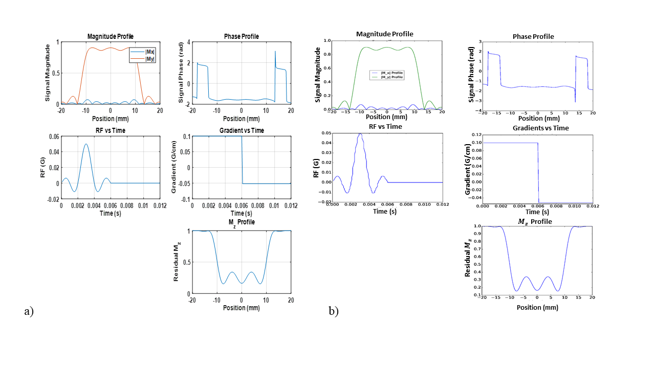
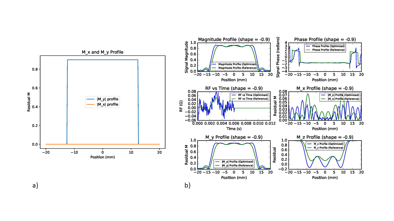
Experiments: We first replicated the Bloch simulation on a quantum-inspired simulator based on a custom implementation of the fourth order Runge-Kutta (RK4) method8. It was validated against the same simulation using MATLAB9. The capability of the quantum-inspired optimizer was then tested to optimize an RF pulse given the magnetization profile (figure 2a) and the gradient waveform (figure 1a). The desired magnetization profile was specified as:
$$ M(x)=[M_x,M_y,M_z] \begin{cases} [0,0,1]& \text{if } x\, is \,outside\, the\, slice \\ [0, sin(\alpha), cos(\alpha)]& \text{else} \end{cases}$$
where $$$\alpha$$$ was the flip angle. In this experiment, the regularization factor was weighted on the RF pulse’s power, with a constant multiplier of 0.1. 2000 points were simulated. In this example, the optimization algorithm was based on Microsoft’s quantum-inspired implementation of Simulated Annealing (SA). We optimized in the time domain, which resulted in jagged output; therefore, we also explored the Gaussian Wavelets domain, as well as Sinc Parameterization to reduce cost in timing and constraining pulse smoothness.
Results
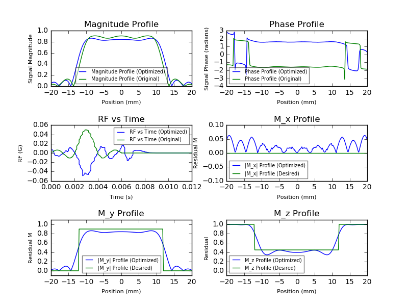
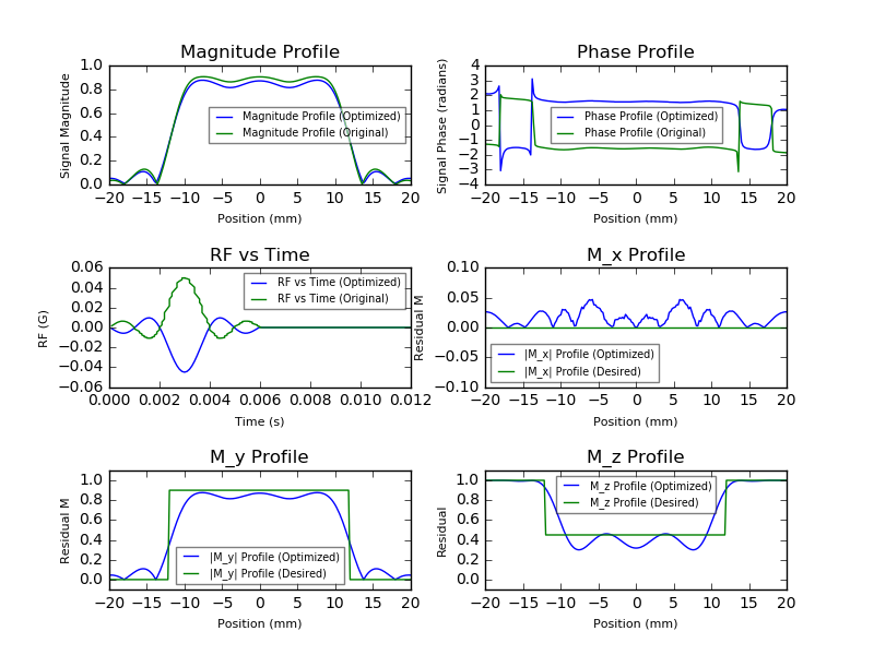
The result in figure 1 shows good agreement between outputs from a quantum-inspired simulator and traditional approaches. Figure 2b shows the result of direct time domain optimization, where the optimized RF pulse results in smaller side lobes as well as a more homogenous magnitude profile than a Sinc pulse. Figures 3 and 4 shows the result of optimization in the Gaussian wavelet domain and Sinc parameterization, respectively, in an attempt to constrain the RF pulse smoothness. The resulting pulse shape in the Gaussian domain optimization is less jagged than its time domain counterpart. The magnitude profile has a smoother passband than the reference simulation. The Sinc parametrization output shows that the optimizer is able to converge to the theoretical pulse shape.Discussion and Conclusions
This is a preliminary study on the capability of quantum-inspired optimization algorithms for RF pulse design. The results show that the optimizer is capable of calculating RF pulses that agree with theoretical pulse shapes and more optimized outputs depending on the domain of optimization. In the future, when physical limitations are incorporated into the cost function, we will be able to optimize both the RF pulse profile and the gradient profile, which allows us to create RF pulses for more interesting spatial profiles. Furthermore, with hardware nonlinearity built into the optimizer, the output waveforms will be able to account for hardware imposed errors.Acknowledgements
This material is based upon work supported by Siemens Healthineers, Microsoft, the National Science Foundation Graduate Research Fellowship under Grant No. CON501692, and NIH grant 1R01EB016728References
- Pauly, J., Nishimura, D. & Macovski, A. A k-space analysis of small-tip-angle excitation. Journal of Magnetic Resonance 213, 544–557 (2011).
- Conolly, S., Nishimura, D. & Macovski, A. Optimal Control Solutions to the Magnetic Resonance Selective Excitation Problem. IEEE Transactions on Medical Imaging 5, 106–115 (1986).
- Pauly, J., Roux, P. L., Nishimura, D. & Macovski, A. Parameter relations for the Shinnar-Le Roux selective excitation pulse design algorithm [NMR imaging]. IEEE Transactions on Medical Imaging 10, 53–65 (1991).
- Conolly, S., Nishimura, D., Macovski, A. & Glover, G. Variable-rate selective excitation. Journal of Magnetic Resonance (1969) 78, 440–458 (1988).
- Lee, D. et al. VERSE-Guided Numerical RF Pulse Design: A Fast Method for Peak RF Power Control. Magn Reson Med 67, 353–362 (2012).
- Anand, C. K., Stoyan, S. J. & Terlaky, T. The gVERSE RF Pulse: An Optimal Approach to MRI Pulse Design. in Modeling, Simulation and Optimization of Complex Processes 25–48 (Springer, Berlin, Heidelberg, 2008).
- Max-SAT 2016 - Eleventh Max-SAT Evaluation. Available at: http://maxsat.ia.udl.cat/results-incomplete/. (Accessed: 5th November 2018).
- Press, W. H. & Vetterling, W. T. Numerical recipes: the art of scientific computing. (Cambridge Univ. Pr., 1988).
- Hargreaves, B. Bloch Equation Simulation
Figures