4611
B0 shim improvement in the inferior frontal lobe by head-tilting: feasibility and comparison with 3rd order shimming1Department of Biomedical Engineering, Sungkyunkwan University, Suwon, Korea, Republic of, 2Center for Neuroscience Imaging Research, IBS, Suwon, Korea, Republic of
Synopsis
Susceptibility-induced signal dropout and image quality impairment in the gradient-echo based imaging are well known problems in brain MRI at high fields. Here, we experimentally demonstrate the feasibility and benefit of head-tilted brain scan as a means to reduce B0 inhomogeneity and associated gradient echo signal loss in the inferior frontal lobe (IFL), and compare the shim improvement with simulated 3rd order shimming in the whole brain.
Introduction
The signal dropout and image quality degradation in gradient echo (GRE) images due to air-tissue susceptibility difference, especially in the inferior frontal lobe (IFL), are well documented.1-5 The GRE signal loss due to intra-voxel dephasing cannot be compensated by post-processing alone. Many authors published methods to address the source of the loss by improving local B0 shimming.2-5 Previous studies 6,7 have reported that changing of head orientation with respect to the main magnetic field resulted in better shimming in the IFL6 and the whole brain on the average.7 Such an approach, however, has not yet been shown to benefit actual neuroimaging scans such as EPI. In this work, we present an improved subject handling method to facilitate brain scans in a head-tilted position, and demonstrate its benefits in B0 shimming and signal recovery in the IFL region.Methods
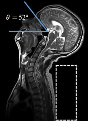
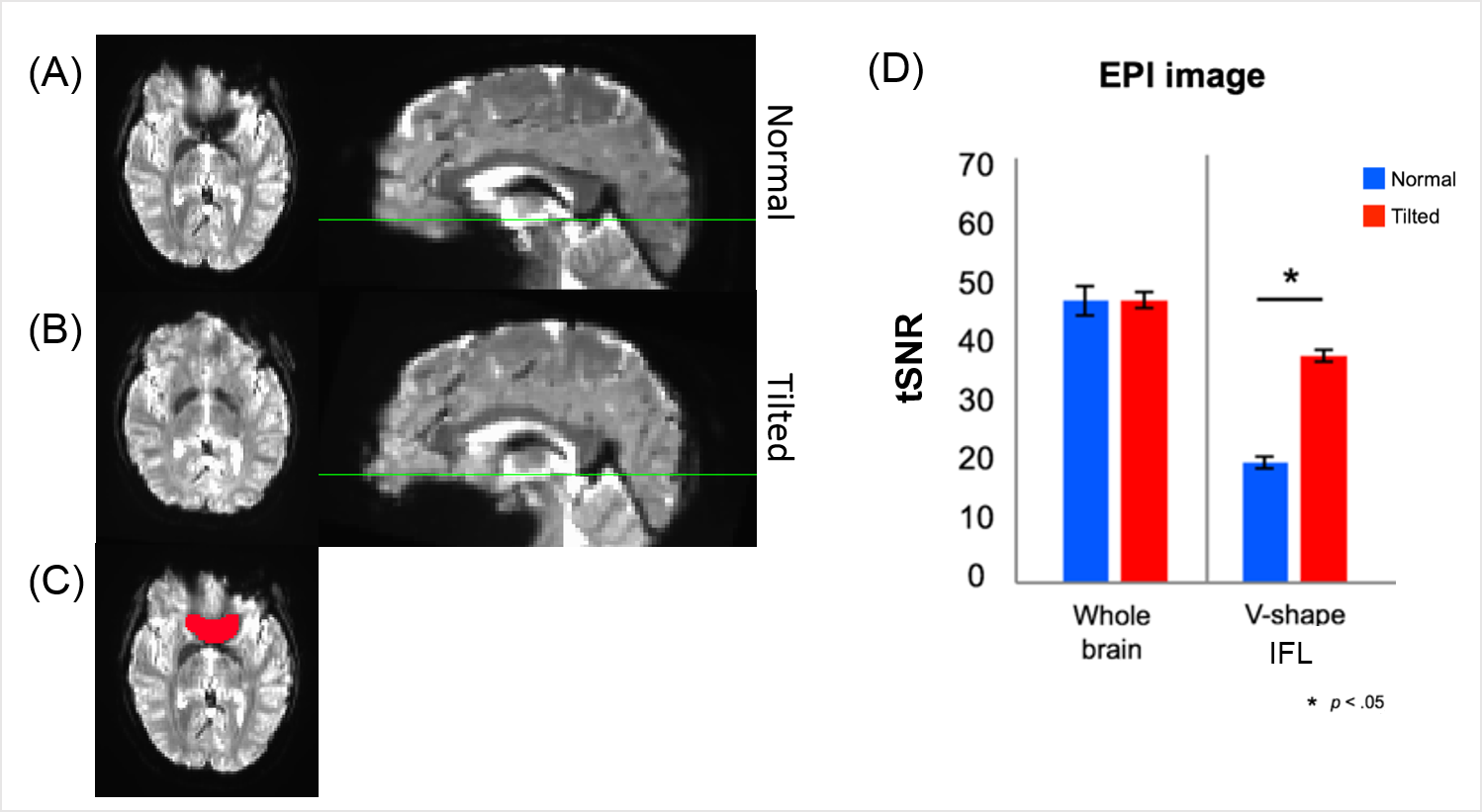
Twelve healthy subjects (male/female = 6/6; age = 21~44) were scanned with normal and tilted (chin-up) head orientations in a 3T scanner (Siemens Prisma) with a 20-channel head-and-neck array. The scanner had full 2nd order shim capability. Eleven subjects were scanned with B0 mapping (TR/TE=23/2.9, 5.4 ms, flip angle=15°, pixel size=3.43x3.43 mm2, slice=2 mm), T1-MPRAGE (TR/TE=2200/2.44 ms, flip angle=8°, voxel size=1 mm isotropic) and GRE-EPI for fMRI (TR/TE=4000/37 ms, flip angle=90°, voxel size=2 mm isotropic, 81 volumes, repeated twice). One subject underwent a multi-echo GRE scan (TR=47 ms, TE=7 to 42 in 5 ms steps, flip angle=20°, pixel size=0.53x0.53 mm2, slice=0.8 mm) in each head orientation. The total scan time in all cases was about 20 minutes including localizer and adjustment scans. For the tilted-orientation scans the subject’s torso was elevated 10-12cm using foam pads under the back, after which the head naturally dropped in the coil housing (Figure 1). This ‘supine star-gazing’ posture resulted in tilt angles between 33° and 56° without excessive neck strain; all 12 subjects reported acceptable scan experience in a post-scan survey. For analysis, the EPI images obtained in both orientations were aligned to the normally-oriented T1-weighted image. The temporal signal-to-noise (tSNR) of the EPI data was calculated both in the whole brain and in the IFL region. For the latter, a 3D, ‘V-shaped’ mask was manually drawn on the normal-orientation EPI corresponding to areas with susceptibility-induced signal loss. B0 maps were obtained from the double-echo GRE phase images. We performed a full 3rd order shim simulation on the normal-orientation B0 maps. The standard deviation (SD) of B0 and the peak B0 gradient in the orbital gyrus ROI (Brainnetome atlas 8) were compared between the two orientations and with the 3rd order shim case.Results
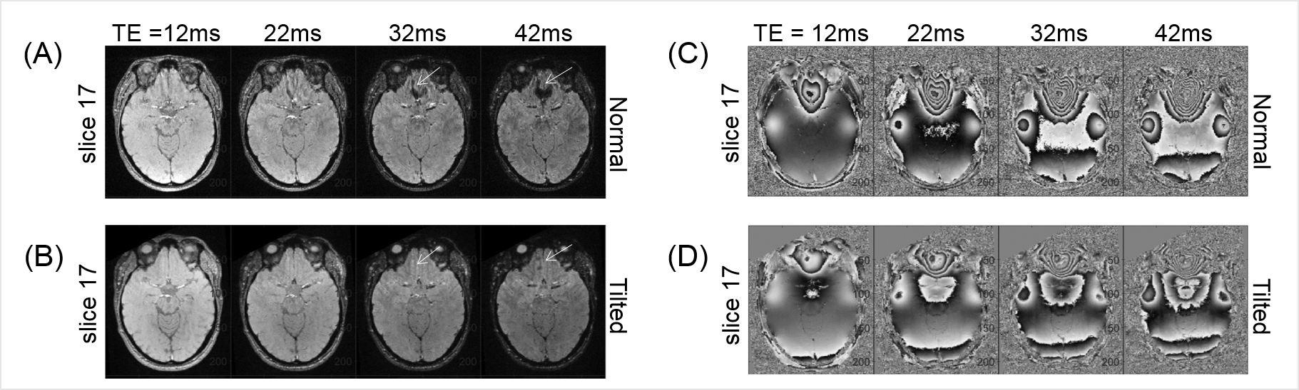
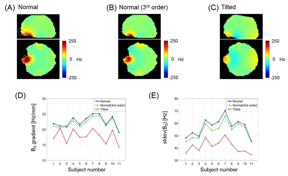
Head-tilted brain scan clearly improved B0 homogeneity in the IFL region. Figure 2A illustrates how the IFL signal loss advances with TE in a normal-orientation scan, leading to apparent signal voids indicated by the arrows; this is not seen in the tilted scan (Fig. 2B). In addition, much stronger phase wrapping is observed in the normally-oriented scans (Fig 2C-D). Figure 3A-B shows representative EPI intensities, showing dramatic reduction of signal drop-out in an axial plane close to the nasal cavity by head-tilting. The signal recovery made direct impact on the tSNR in repeated EPI scans. While the tSNR of the whole brain did not significantly differ between the head orientations, the tSNR in the IFL region nearly doubled by head tilting (Fig 3D). Figure 4A-C shows representative axial and sagittal B0 maps at the two head orientations and the 3rd order shim simulation. The peak B0 gradient and B0 SD in the orbital gyrus (Fig. 4D-E) are reduced much more by tilting (mean 21% and 27% reduction for B0 gradient and SD respectively) than by the 3rd order shimming (mean 2.7% and 5.1%, respectively).Discussion
We confirmed that tilted-head scans for healthy volunteers reduced susceptibility-induced signal dropout and improved image quality in GRE-based imaging without any modifications to the hardware, sequence, and post-processing. The method enabled better B0 shimming than with the whole-head 3rd order shimming in the orbital gyrus. While the experiment was limited to 20-min scans and a relatively small number of cooperating volunteers, our method has a potential to benefit neuroimaging scans in the IFL that are sensitive to B0 inhomogeneity. An RF coil array which is better designed (in terms of mount and coil placement) for head-tilted imaging could further enhance subject comfort and SNR. Our subject handling method could also facilitate multi-orientation scans for tissue anisotropy measurement and artifact-reduced quantitative susceptibility mapping.9-10Acknowledgements
This work was supported by IBS-R015-D1.References
[1] Clare, Stuart, John Evans, and Peter Jezzard. "Requirements for room temperature shimming of the human brain." Magnetic Resonance in Medicine 55 (2006): 210-214.
[2] Hsu, Jung‐Jiin, and Gary H. Glover. "Mitigation of susceptibility‐induced signal loss in neuroimaging using localized shim coils." Magnetic Resonance in Medicine 53 (2005): 243-248.
[3] Juchem, Christoph, et al. "Magnetic field homogenization of the human prefrontal cortex with a set of localized electrical coils." Magnetic Resonance in Medicine 63 (2010): 171-180.
[4] Cusack, Rhodri, et al. "An evaluation of the use of passive shimming to improve frontal sensitivity in fMRI." Neuroimage 24 (2005): 82-91.
[5] Yang, Sejung, et al. "Local in vivo shimming using adaptive passive shim positioning." Magnetic resonance imaging 29 (2011): 401-407.
[6] Heberlein, Keith, and X. Hu. "Improved shim by subject head positioning." Proceedings of the 9th Annual Meeting of ISMRM, Glasgow, Scotland (2001), p.1157
[7] Tyszka, J. Michael, and Adam N. Mamelak. "Quantification of B0 homogeneity variation with head pitch by registered three-dimensional field mapping." Journal of Magnetic Resonance 159 (2002): 213-218.
[8] Fan, Lingzhong, et al. "The human brainnetome atlas: a new brain atlas based on connectional architecture." Cerebral cortex 26 (2016): 3508-3526.
[9] Liu, Chunlei. "Susceptibility tensor imaging." Magnetic Resonance in Medicine 63 (2010): 1471-1477.
[10] Liu, Tian, et al. "Calculation of susceptibility through multiple orientation sampling (COSMOS): a method for conditioning the inverse problem from measured magnetic field map to susceptibility source image in MRI." Magnetic Resonance in Medicine 61 (2009): 196-204.
Figures