4605
2D Imaging near Metallic Implants at 0.5T using High Time-Bandwidth Product RF pulses1Research and Development, Synaptive Medical, Toronto, ON, Canada, 2Physics and Astronomy, Western University, London, ON, Canada
Synopsis
There are several benefits to reducing the main magnetic field strength including a reduction of imaging artefacts near metallic implants and the ability to significantly increase the peak B1+ of the RF pulses due to the reduction in SAR penalty. This enables higher time-bandwidth product (TBP) for a given RF pulse duration. In this work, we utilized high TBP RF pulses on a high-efficiency transmit coil and a 0.5T MR system to reduce through-plane distortions caused by metallic implants. In addition to characterizing through-plane distortions, the impact of these pulses on in-plane distortions and SAR were also characterized.
Introduction
Lower magnetic field strengths offer several advantages for MR imaging near metallic implants. The most prominent advantage is that the severe magnetic field inhomogeneities caused by the large magnetic susceptibility difference between metallic implants and tissue are reduced1. As a result, artefacts associated with these inhomogeneities—including in-plane1-4 and through-plane distortion3,4 and signal loss due to dephasing4—are reduced. A less prominent advantage is that specific absorption rate (SAR) is also decreased at lower field strengths, which enables the use of higher SAR radiofrequency (RF) pulses. The purpose of this work is to utilize a high-efficiency transmit (Tx) coil (>50µT) and the low SAR of a 0.5T MR system to reduce through-plane distortions near metallic implants with high peak B1+, high time-bandwidth product (TBP), RF pulses. The impact of these RF pulses on in-plane and through-plane distortions as well as SAR were characterized.Methods
All acquisitions were acquired using an in-house designed head-specific 0.5T MR system equipped with a high-efficiency transmit birdcage (B1+ > 50 µT) and a high-performance gradient set able to produce a max gradient strength and slew rate of 100 mT/m and 400 T/m/s per axis respectively.
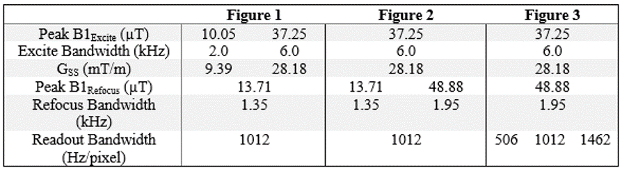
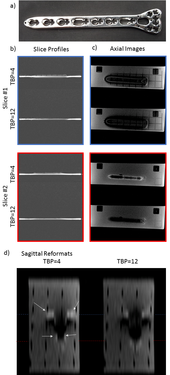
A phantom consisting of a 316L stainless steel compression plate (Fig. 1a), grids, and a doped water solution (12.5mM CuSO4) was constructed. Slice profiles and 2D spin echo images were acquired with various Shinnar-Le Roux5 excitation/refocusing pulses. Slice profile imaging parameters were: RF pulse duration = 2.0 ms, matrix size = 200 x 200, receiver BW = 1250 Hz/pixel, TE = 16 ms, field of view = 200 mm, slice thickness = 5 mm, slice gap = 0.5 mm. For all spin echo acquisitions the following imaging parameters were held constant: RF pulse duration=2.0 ms, matrix size = 192 x 192, TE = 10.5 ms, field of view = 192 mm, slice thickness = 5 mm, slice gap = 0.5 mm. The receiver bandwidth of the 2D spin echo acquisitions was varied to highlight the change in in-plane distortion due to modifying the refocusing bandwidth. A summary of the different RF pulse properties and receiver bandwidths used in each figure are shown in Table 1.
Full-wave electromagnetic simulations were performed in CST microwave studio utilizing a physical model of the high-efficiency transmit birdcage coil. Local 10-g SAR was computed across a homogeneous phantom (dimensions: 9 x 35 x 35 cm and relative permittivity equal to 80).
Results
Figure 1 shows the use of high TBP excitation pulses to reduce through-plane distortion. The slice profiles of excitation pulses with TBP=12 show substantially reduced slice distortions from the compression plate compared to TBP = 4. Furthermore, the high bandwidth excitation results in greater signal dropout near the implant where the off resonance is greatest.
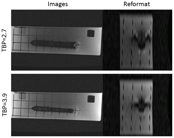
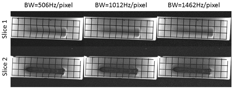
Figure 2 shows that increasing the refocusing bandwidth recovers signal near the metallic implant. This comes at the cost of increased in-plane frequency encoded related distortions. Increasing the receiver bandwidth (Figure 3) can be used to mitigate this effect, albeit at the cost of SNR.
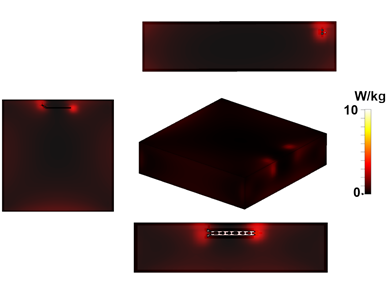
Figure 4 demonstrates 10-g local SAR. Maximum 10-g SAR met FDA requirements at 4.52 W/kg for the excitation and refocusing pulse train (50 µT peak, 4.5 µT average, played continuously).
Discussion
We used high TBP RF pulses to reduce through-plane distortions near a 316L stainless steel compression plate. This method is not seen as a replacement for 3D-MSI techniques3,6,7 which are clearly superior in regimes near a metallic implant. Instead we see this as a method to acquire fast images with good robustness to slice distortions and well defined in-plane distortions.
An alternative to reduce through-plane distortions would be to invert the slice select gradient between excitation and refocusing pulses, a method used for 2D-MSI.6 Combining the gradient reversal technique with straighter slice profiles would translate to fewer spectral offsets needed for full off-resonance coverage.
Bulk distortions (Δx, voxels) along the readout dimension2 are described by Δx=Δf/BWpix where Δf is the off-resonance frequency (Hz), and BWpix is the readout bandwidth (Hz/voxel). The TBP required can be calculated when given a maximum acceptable displacement and readout bandwidth. Frequency encode distortions could be reduced further by implementing view angle tilting.9
High TBP RF pulses result in large slice-select gradient amplitudes and high slew rate. These modifications to the slice-select waveform can have device-specific effects on both image quality and safety10,11 that should be considered.
Conclusions
This work demonstrates that one can utilize high available B1+ and SAR headroom to image with large TBP RF pulses, in order to mitigate through-plane distortions near metallic implants.Acknowledgements
The authors acknowledge the support of the Mitacs Accelerate post-doctoral fellowship.References
1. Smith MR, Artz NS, Wiens C, Hernando D, Reeder SB. Characterizing the limits of MRI near metallic prostheses. Magn. Reson. Med. 2015;74:1564-1573.
2. Koch KM, King KF, Carl M, Hargreaves BA. Imaging near metal: The impact of extreme static local field gradients on frequency encoding processes. Magn. Reson. Med. 2013;71: 2024–2034.
3. Koch KM, Hargreaves BA, Pauly KB, Chen W, Gold GE, King KF. Magnetic resonance imaging near metal implants. J. Magn. Reson. Imaging 2010;32:773–787.
4. Hargreaves BA, Worters PW, Pauly KB, Pauly JM, Koch KM, Gold GE. Metal-Induced Artifacts in MRI. American Journal of Roentgenology 2011;197:547–555.
5. Pauly J, Le Roux P, Nishimura D, Macovski A. Parameter relations for the Shinnar-Le Roux selective excitation pulse design algorithm. IEEE Transactions on Medical Imaging. 1991;10(1):53–65.
6. Lu W, Pauly KB, Gold GE, Pauly J, Hargreaves B. SEMAC: slice encoding for metal artifact correction in MRI. Magn Reson Med. 2009; 62:66–76.
7. Koch KM, Brau AC, Chen W, Gold GE, Hargreaves BA, Koff M, McKinnon GC, Potter HG, King KF. Imaging near metal with a MAVRIC-SEMAC hybrid. Magn Reson Med 2011;651:71–82.
8. Hargreaves BA, Taviani V, Litwiller DV, Yoon D. 2D multi‐spectral imaging for fast MRI near metal. Magn. Reson. Med. 2018;79:968-973.
9. Cho ZH, Kim DJ, Kim YK. Total inhomogeneity correction including chemical shifts and susceptibility by view angle tilting. Med Phys 1988;15:7–11.
10. Graf H, Steidle G, Schick F. Heating of Metallic Implants and Instruments Induced by Gradient Switching in a 1.5-Tesla Whole-Body Unit. J. Magn. Reson. Imaging 2007;26:1328-1333.
11. Graf H, Steidle G, Martirosian P, Lauer UA, Schick F. Metal artifacts caused by gradient switching. Magn. Reson. Med. 2005:54:231-234.
Figures