4604
Pileup Artifact Correction Near Metal Implants Using Deep Neural Networks and Spectral K-Space Modulation1Radiology, Medical College of Wisconsin, Milwaukee, WI, United States
Synopsis
Three-dimensional multispectral imaging (3D-MSI) techniques used for metal artifact correction can provide relatively clear images near most metallic implants. However, within localized regions near some implants, 3D-MSI demonstrate residual artifacts that are unlike any other artifact previously seen in MR images. These confounding features in 3D-MSI are known as “pileup” or “ring” artifacts. In this study, we present a novel approach to residual artifact correction in 3D-MSI that relies on 1) deep neural networks, 2) physical modeling of local gradients, and 3) k-space modulation and replacement of spectral data in compromised regions
Introduction
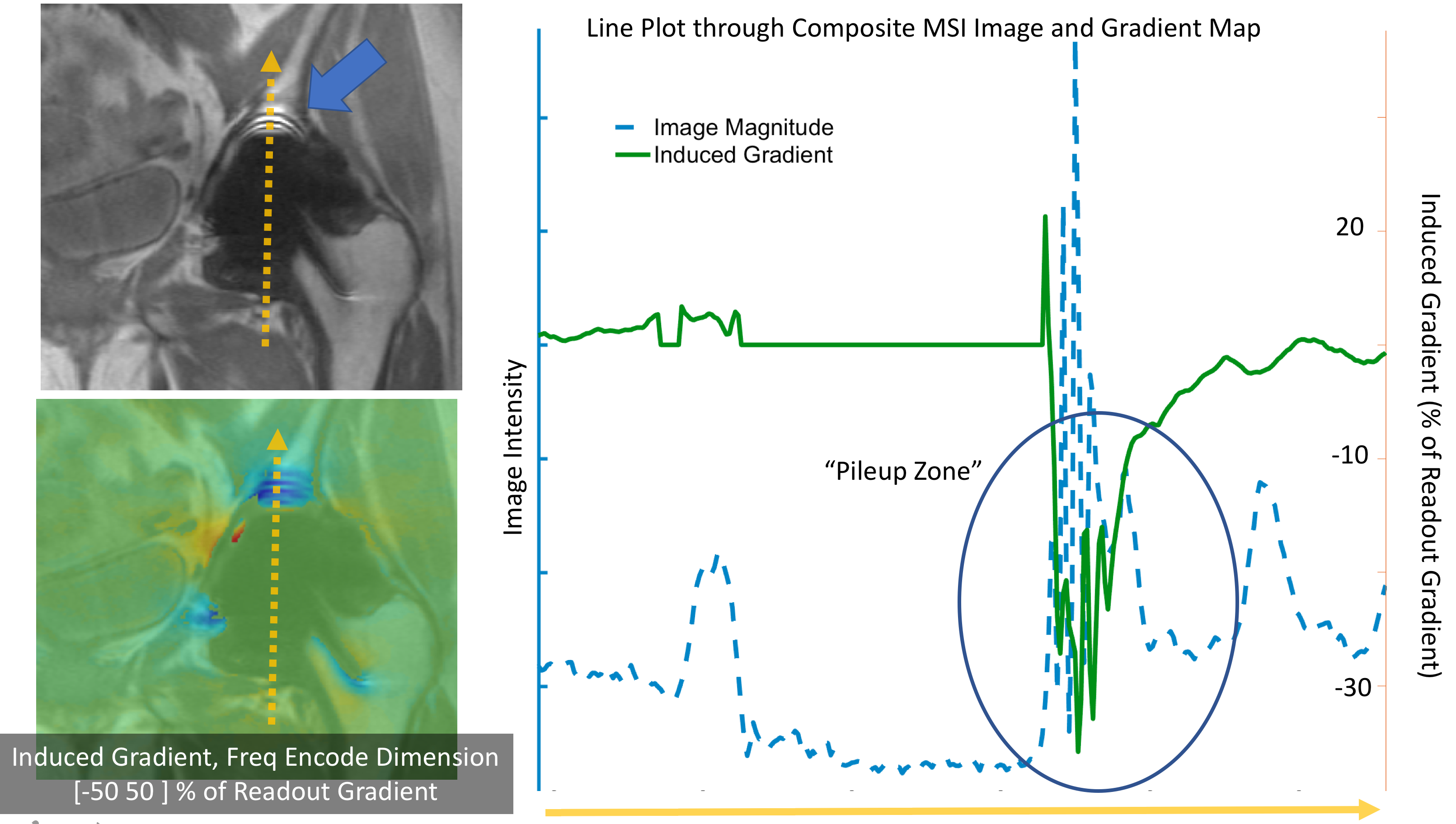
Three-dimensional multispectral imaging (3D-MSI) techniques used for metal artifact correction [1,2,3] can provide relatively clear images near most metallic implants. However, within localized regions near some implants, 3D-MSI demonstrate residual artifacts that are unlike any other artifact previously seen in MR images. These residual “pileup” or “ring” artifacts arise because 3D-MSI techniques can substantially reduce, but cannot fully eliminate spatial encoding errors and signal-reduction effects in MRI. Figure 1 provides a demonstration 3D-MSI pileup artifacts and illustrates their source as a function of local induction gradients near the implant interface.
Previous work has characterized the physics driving 3D-MSI pileup artifacts [4]. In this study, we present a novel approach to residual artifact correction in 3D-MSI that relies on 1) deep neural networks, 2) physical modeling of local gradients, and 3) k-space modulation and replacement of spectral data in compromised regions
Methods
Artifact Localization: A major challenge with previous attempts at residual artifact correction in 3D-MSI was the difficulty in focusing in on specific regions of artifact. Here, we utilize the power of deep learning to identify patterns of pileup artifact in 3D-MSI images. For this proof-of-principle study, 36 3D-MSI total hip replacement image sets were utilized to curate a training set. A 2D-UNET was utilized to train the network to identify regions of pileup artifact. The encoder-decoder (UNet) was created using PyTorch. Each encoder step consisted of two 3x3 2D convolution layers followed by a single 2x2 max pooling layer, while decoding was performed using a single 2x2 up-convolution followed by two 3x3 2D convolution layers. The final layer was a single 1x1 2D convolution which created a prediction (feature) map of the same size as the input images. The model had a depth of 4, meaning there were a total of 3 max pooling and up sampling steps.
For each epoch during training, the input data was divided into batches of 4. After each training pass, the loss was calculated using the binary cross entropy loss function and model parameters were updated. Once all training batches were complete, the updated model was applied to a separate validation set, and the loss was calculated using the same loss function. If the loss improved from the previous epoch, the latest model was saved. This training process was repeated for 200 epochs.
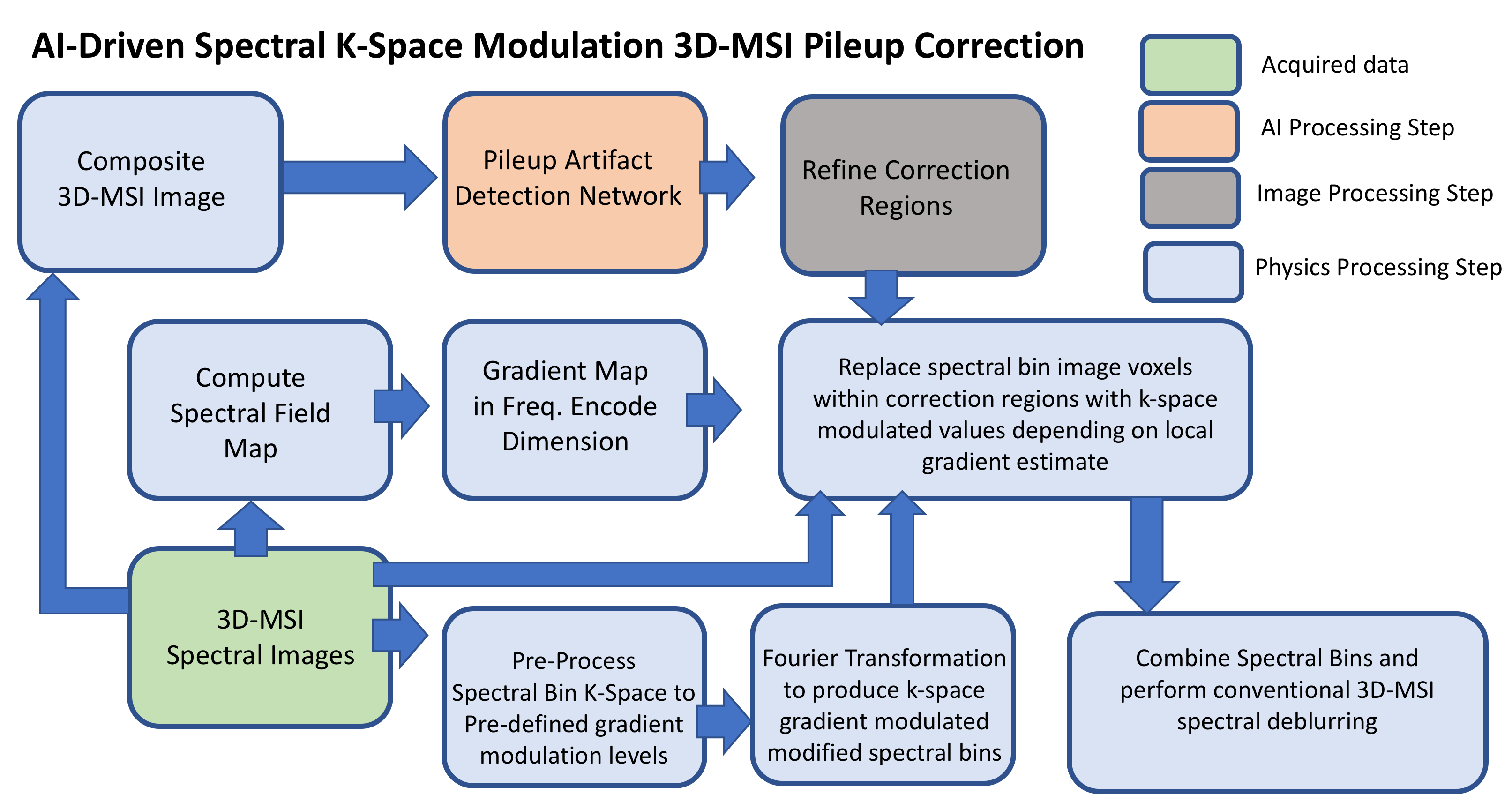
Artifact Repair: There are two classes of artifacts in extreme induced gradient regions: 1) signal pileup and 2) signal loss. Signal loss cannot be recovered using any post-processing approach. Pileup can be improved, but there are physical limitations to these improvements. In regions of pileup artifact, local induction gradients have effectively reduced the local frequency encoding gradient, and caused a spatial compression of signal. The resulting resolution loss is a Nyquist sampling issue, that cannot be repaired by re-gridding data. However, the manifestation of pileup artifacts can be reduced if k-space is modulated appropriately to account for the loss of sampling integrity. Our initial tests found that local gradient estimates, computed from 3D-MSI field maps [3], can provide insight on how much k-space compensation to apply in different regions. Using the regions identified with the deep-learning pattern-recognition algorithm, individual spectral bins were locally corrected using this approach. Figure 2 provides the workflow of this correction algorithms.
Results and Discussion
The training of the artifact detection network was sufficient to identify regions of severe pileup. Utilizing the training labels, a voxelwise analysis showed that the average detection score (probability of being in region of pileup) within each of the labeled ROIs was over 3 times that of the outside tissue regions (0.1467 inside vs 0.0582 outside). Empirically, the utility of the network was greatly improved if a high threshold was used to identify regions of pileup (0.7). As a result, some regions of modest pileup were missed. Further training with a larger curated dataset will be required to improve this performance.
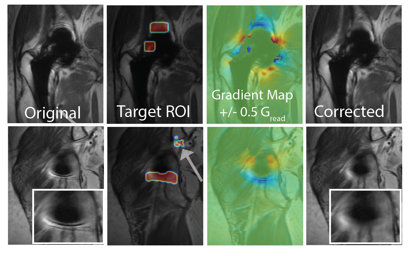
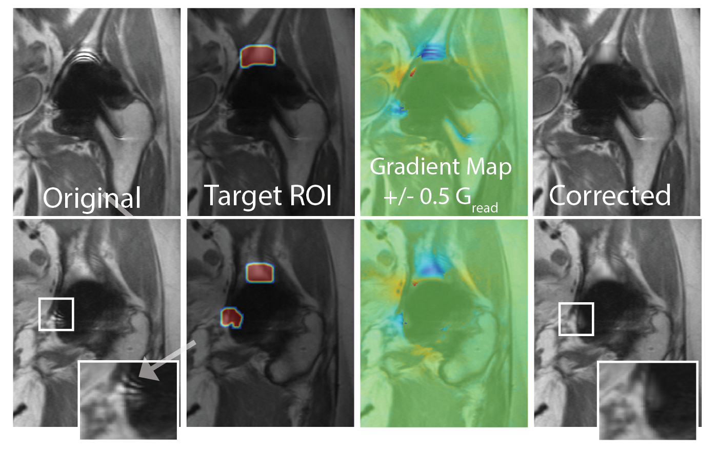
Figures 3 and 4 provide demonstrations of the algorithm performance in regions of severe and modest pileup in two total hip replacements. In Figure 3, the severe artifact at the top of the acetabulum is removed, revealing a cleaner image with a loss of resolution (dictated by the physics which created the pileup artifact). The lower row provides an example within this dataset at the edge of the implant, where modest pileup rings are removed while maintaining reasonable resolution throughout the correction. The amount of blurring after correction is dictated by the local gradient field estimates, which is indicative of the Nyquist undersampling that was effectively performed during data acquisition.
Acknowledgements
This work was funded by a technology development grant from GE Healthcare.References
1. Lu W, Pauly KB, Gold GE, Pauly J, Hargreaves B. SEMAC: slice encoding for metal artifact correction in MRI. Magn Reson Med 2009; 62:66–76.
2. Koch KM, Lorbiecki JE, Hinks RS, King KF. A multispectral three- dimensional acquisition technique for imaging near metal implants. Magn Reson Med 2009;61:381–390.
3. Koch KM, Brau AC, Chen W, Gold GE, Hargreaves BA, Koff M, McKinnon GC, Potter HG, King KF. Imaging near metal with a MAVRIC-SEMAC hybrid. Magn Reson Med 2011;651:71–82. [
4 Koch, K. M., King, K. F., Carl, M., & Hargreaves, B. A. (2014). Imaging near metal: The impact of extreme static local field gradients on frequency encoding processes. Magnetic Resonance in Medicine, 71(6), 2024–2034. http://doi.org/10.1002/mrm.2486
Figures